


VIS-CAM System
20 Installing the Vehicle Imaging Subsystem
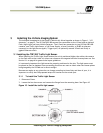
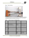
2. Align the camera enclosure mounting surface with the hole pattern of the camera mount and
secure it to the camera mount with the five provided ¼-20 hex bolts.
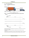
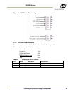
3. Attach the camera, with mount, to the mounting structure. The hole pattern is shown in Figure 15
Below
Figure 15. Camera mount template.
4. Route the camera end of the camera cable according to the camera IAW local electrical code
Requirements
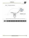
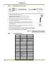
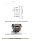
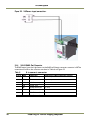
5. The jacket is removed from the cable in the camera end and the wires are stripped as shown in the
Figure 16 below. There are two sets of four twisted pairs. Four of the pairs are for ethernet signals.
These pairs are individually foil shielded and have a common braid shield. The other four pairs are
individually foil shielded without the common braid shield. The shield on the Ethernet pairs must
be run as close to the connector as possible. All wires must be stripped for insulation app. 7mm.
Figure 16. Camera cabling as it appears before electrical installation.
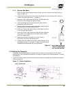
6. The cable is separated into the Ethernet part (with the braid shield) and the power and control
part (the rest). Each part is fastened with cable ties to the respective cable relief’s on the terminal
block X4 on the VIS-CAM I/O Board.