


System Set-Up 35
VIS-CAM System
camera settings should already be correct for the site installation, but it is a good idea to verify that
this is true before proceeding. The Setup Computer is now properly configured to support lens
adjustments and camera aiming.
4.1.6 Connect the Setup Computer to the Camera
• Position the Setup Computer next to the camera being aligned. If the alignment is conducted in
bright sunlight, shield the monitor screen with a hood to make it visible. Make sure that no
portion of the computer or cables interfere with the camera’s view of the road.
• Connect the Setup Computer’s network adapter with the camera network. This can be done
directly to the I/O boards X1 and X3 connectors or using a local Ethernet switch. It is preferable
to use a local Ethernet switch instead of a local direct connection to the I/O board. A direct
connection between the Setup computer and the camera will disconnect the camera from the
site LAN and thereby disconnect the light sensor as well.
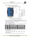
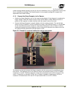
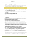
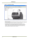
Figure 30. Example of a network connection using a local switch.
The network connection between the Setup computer and the camera can be established using a
local switch. Two separate ports of the Ethernet Switch are connected directly to the I/O board
connectors X1 and X3. The Setup computer is then also connected to one of the free ports on the
switch. If the switch is running on 24V dc, the I/O board is capable of supplying up to 0.5A on
connector X15 located next to X1 and X3. The pin marked with #1 on X15 is +24V dc.