


VIS-CAM System
72 Appendix B: J-Panel Functional & Connector Description
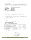
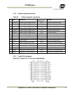
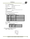
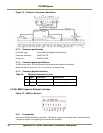
6.3.6 Indicators
There are two LED indicators mounted at the connector:
Table 23 LED indicators
LED label LED color Indication
Trig-1 Green Indicates generation of trigger pulse to camera
Of
f
No trigger pulse
LC DATA LED not mounted
Powe
r
Green 24V present at connector pin 10
red No 24V at connector pin 10
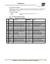
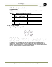
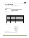
6.3.7 Switches
There are two switches located at the connector:
Table 24 Connector switches
Switch label Switch color
Function
S1 TRIG CAM-1 Push bottom
Generates a trigger pulse to the camera
S5 TRIG POLARITY Slide Selects trigger polarity
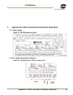
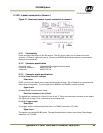
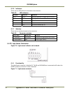
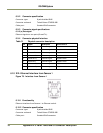
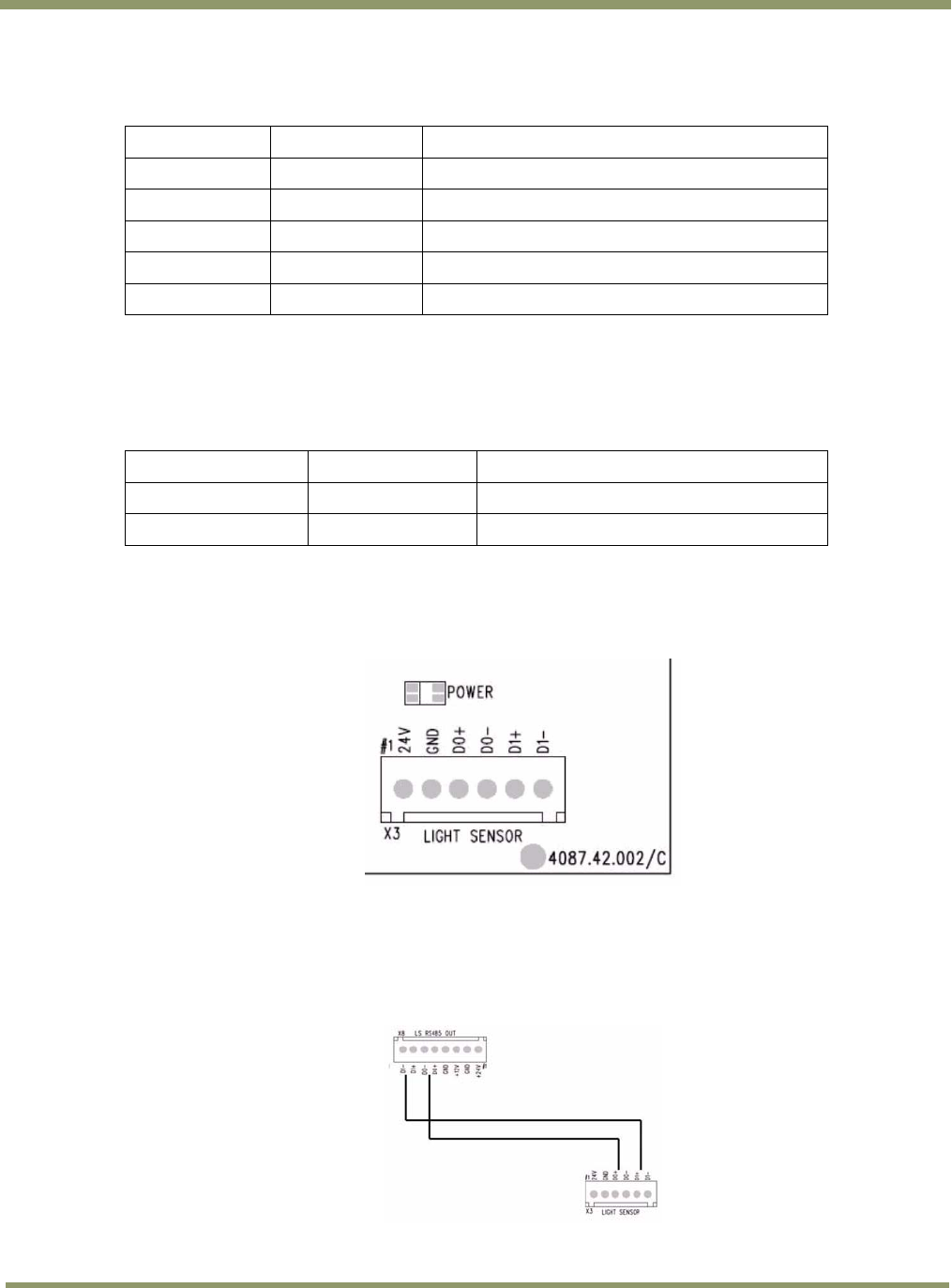
6.4 X3: Light Sensor Connection
Figure 70. Light sensor indicator on the board
6.4.1 Functionality
The Light Sensor connector is labelled X3. The D0 and D1 RS485 bus is connected to X8 where the
RS485 to ethernet converter is to be connected.
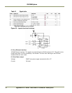
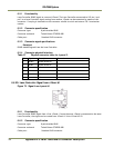
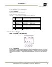
Figure 71. Light sensor connector