


Installing the Vehicle Imaging Subsystem 17
VIS-CAM System
3 Installing the Vehicle Imaging System
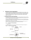
The individual components of the system is electrically linked together as shown in Figure 1, “VIS
elements,” on page 2. The VIS CAM 300/400 camera has connections to the J-Panel and an optional
Flash, Night Light and Laser Vehicle Detector. The J-Panel has connection to two VIS CAM 300/400
cameras, one Traffic Light Sensor, a 24V Power Supply, a Lane Controller, a RS485-to-ethernet
converter for the light sensor signals, Trigger input, an optionally second J-Panel and finally a
gigabit Ethernet switch.
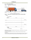
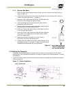
3.1 Installing the TNF-300 Traffic Light Sensor.
When installing the Traffic Light Sensor ensure the unit is positioned higher than either the camera
or the flash unit so the A-side is in direct sun whenever the targeted vehicles license plates are. See
Section 2.1 on page 6 for general site layout guidelines.
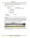
It is extremely important the light sensor be properly positioned at the site. The light sensor must
be placed so that no shadows from surrounding structures are cast on side A when the license plates
being imaged by the VISCAM are in direct sunlight.
Because sun angles at any given site can change according to time of day and time of year, it is
important to verify that the proposed setup will function on the actual spot.
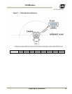
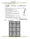
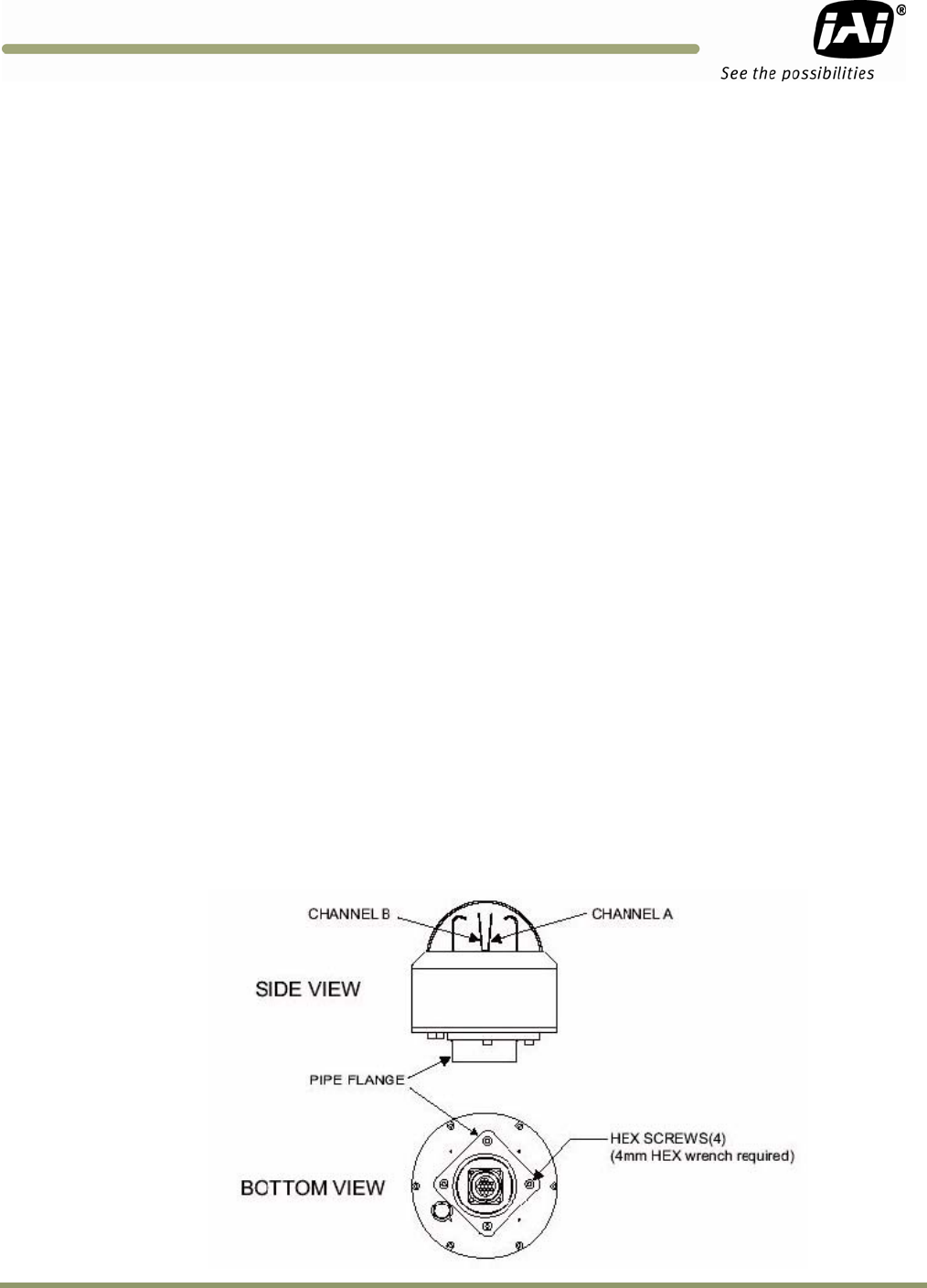
3.1.1 To install the Traffic Light Sensor:
1. Disconnect Power
2. Loosen the four hex screws and remove the flange from the mounting base. See Figure 10.
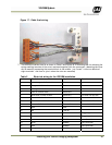
Figure 10. Install the traffic light sensor.