


VIS-CAM System
62 Appendix A: Camera Functional & Connector Description
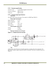
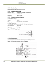
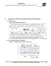
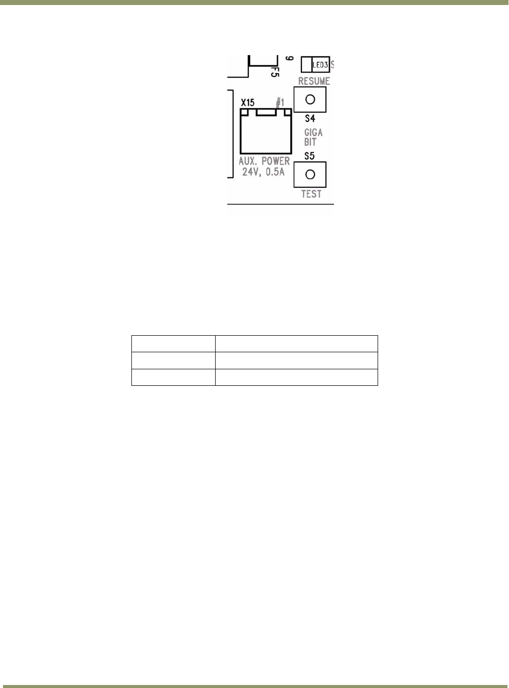
5.7 X15: I/O Board Auxiliary power connector
Figure 62. Auxiliary power connector
5.7.1 Functionality
Power outlet for auxiliary equipment.
5.7.2 Connector physical Interface
Connector: 2 pole WAGO pluggable terminal block
PCB part: WAGO 734-232
Cable part: WAGO 734-202
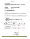
Connector pin # Signal
1 +24V (fused 0.5A) (self resetable)
2 Gnd
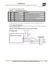
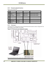
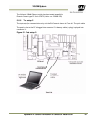
5.8 Cables
In order to comply with EMC regulations the cable must be shielded and the wires must be twisted
pairs. The cable used for the Ethernet signals must be minimum Cat 5e and preferably Cat 6. The
wires used for power must be a minimum 0.5 mm2.
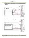
5.8.1 Cable Specifications
5.8.1 (a) Ethernet:
Category Cat 5e or preferably Cat 6
Characteristic impedance 100 Ω
Number of twisted pairs 4
Maximum cable diameter 15 mm
Maximum cable length 100 meters
5.8.1 (b) RS485 and power:
Characteristic impedance 120 Ω
Number of twisted pairs 4
Wire dimension ≥ 0.5mm
2
Maximum cable diameter 15 mm
Maximum cable length 100 meters