


VIS-CAM System
34 System Set-Up
4.1.2 Select a Suitable Vehicle, License Plate, and Plate Stand for the Setup
To accurately set up the Vehicle Imaging Subsystem, the system installers need access to:
1. A vehicle that can be temporarily parked on the road
2. A plate that is:
a. typical in size and color for the site
b. clean, flat and in “like new” condition
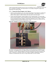
3. An adjustable plate stand that allows the plate to be mounted in a vertical plane, at various
heights above the road, and at variable roll angles. The stand must allow the plate to be placed
at both the nominal plate height and the minimum expected plate height. The stand must also
allow the plate to be rolled at least + or – 10 degrees from horizontal but held firmly in place
once a specific roll angle is selected. The stand should be heavy enough so that the wind will not
blow it over or move it.
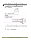
Table 12 Typical minimum plate heights and nominal plate heights:
Plate Height Front of Vehicle
Back of Vehicle
minimum (bottom edge) 8in or 20cm
15in or 38cm
nominal (middle) 16in or 40cm
24in or 60cm
4.1.3 Select the Camera to Align
• If the site employs a single camera per lane, then you can choose any lane to start the
alignment procedure.
• If the site employs multiple cameras regularly spaced across a roadway to provide continuous
fieldof- view coverage from edge to edge, select one of the cameras at either edge of the
roadway to be the first camera to align.
• Align all remaining cameras in order from the first camera aligned to the last camera at the
other side of the roadway. The next camera aligned is always the one adjacent to the camera
most recently aligned.
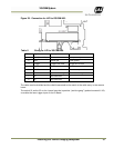
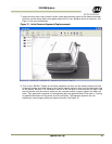
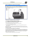
4.1.4 Validate the Installation Geometry
The VIS cameras and vehicle trigger line should have been installed at the locations agreed to by
you and JAI. Typically JAI utilizes a specially developed Excel worksheet to confirm the suitability of
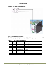
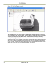
the equipment placement at the site from an image processing perspective. See Figure for an
example worksheet. However, equipment is often not located where the worksheet specifies. It is
therefore imperative that the actual equipment layout at any given site be measured to verify that
the cameras and trigger are located at the desired locations relative to each other. If necessary,
move the camera/trigger positions until the distances required in the worksheet are met. If it is not
possible to move the equipment to the required locations, then the impact of any changes to the
subsequent image processing must be assessed. Enter the actual camera locations into the Input
section of the JAI worksheet and then note the changes in the Results section. If there are any
questions about the suitability of a specific camera/trigger layout, contact your JAI representative
for advice.
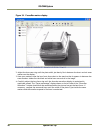
4.1.5 Edit the alignment settings on the Setup Computer
In order to carry out the alignment properly, the ENSetup program has to be configured with two
values from the worksheet. See the ENSetup Program User’s Guide (Video Window Setup section) for
details on changing Video Window properties.
Using the ENSetup program, make sure the “tilt line” and “plate num cols” items on your Portable
Setup computer are exactly the same as the measurements, including the proper plate size
parameters measured in Section 4.1.4, “Validate the Installation Geometry,” on page 32. All other