


VIS-CAM System
50 Appendix A: Camera Functional & Connector Description
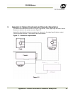
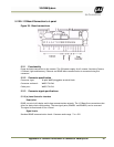
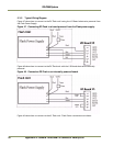
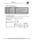
5.2.6 Typical wiring diagram.
Figure 43. Category 5 or 6 wiring diagram.
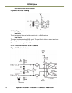
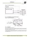
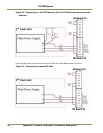
5.3 I/O Board Flash Connection
Figure 44. Flash connections.
5.3.1 Functionality
Output to flash unit. This output is used when only one flash unit is connected. The output is
galvanically isolated using an optocoupler. The isolated part of the electronics on the board can be
powered from the flash unit or from the I/O Board using a 24V DC output on the connector.
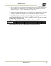
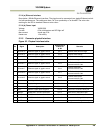
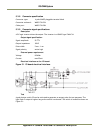
5.3.2 Connector specification
Connector type: 6 pole WAGO pluggable terminal block
Connector on board: WAGO 734-236
Cable part: WAGO 734-206