


Appendix A: Camera Functional & Connector Description 53
VIS-CAM System
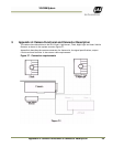
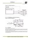
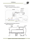
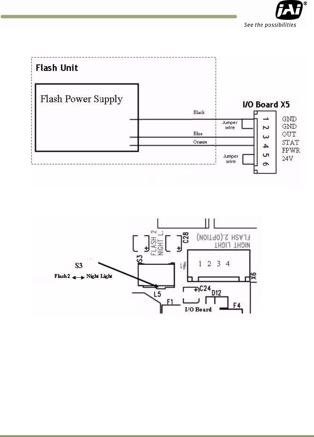
Figure 49. AC flash unit connection.
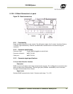
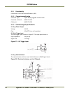
5.3.6 X6: I/O Board Night Light/2nd Flash Connection
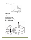
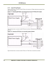
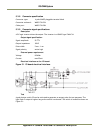
Figure 50. Second flash connection.
5.3.7 Functionality
Output to Night Light or second Flash unit.
When switch S3 is positioned as shown in Figure 50 (to the right), X6 outputs the night light control
signal. When S3 is pushed to the left, X6 outputs the signal for a second flash unit. In this mode the
strobe signal is fed alternately to X5 and X6.
The output is galvanically isolated using an optocoupler. The isolated part of the electronics on the
board is powered from the Night Light or Flash unit. If no power is available from the unit’s power,
it can be taken from X5.