


Installing the Vehicle Imaging Subsystem 27
VIS-CAM System
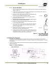
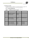
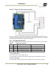
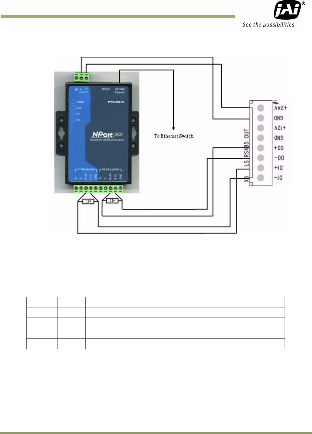
Figure 23. Wiring for the X8 to converter connector.
Up to four cameras can be connected to one Light Sensor using one Moxa Nport 5232 Device Server.
If more than four cameras need to be connected to the same Light Sensor please refer to “Appendix
E: Moxa N-Port 5232 Configuration” on page 93 in this Manual.
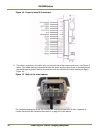
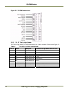
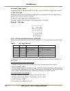
3.3.5 X14 Trigger Input Connector
The Trigger input connection to the J-Panel is connector X14. The connections are listed in Table 7
Table 7 Trigger input connector.
X14 Pin # Signal Description
Connection to
1 Trig0+ Positive Trigger input to camera 0
Trigger device positive terminal
2 Trig0- Negative Trigger input to camera 0
Trigger device negative terminal
3 Trig1+ Positive Trigger input to camera 1
Trigger device positive terminal
4 Trig1- Negative Trigger input to camera 1
Trigger device negative terminal
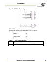
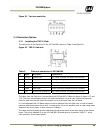
3.3.5 (a) Trigger polarity
The switches S3 and S5 sets the trigger polarity:
If the trigger signal is normally low (no voltage at trigger input) the switch shall be in position
Arrow up - positive going
If the trigger signal is normally high (voltage at trigger input) the switch shall be in position