


VIS-CAM System
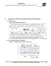
68 Appendix B: J-Panel Functional & Connector Description
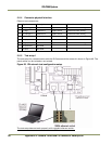
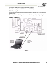
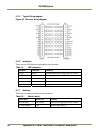
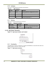
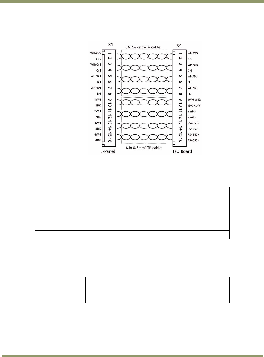
6.2.5 Typical Wiring diagram
Figure 66. Ethernet wiring diagram.
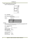
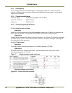
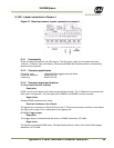
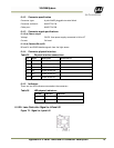
6.2.6 Indicators
There are two LED indicators mounted by the connector:
Table 19 LED indicators
LED label LED color Indication
Trig-0 Green Indicates generation of trigger pulse to camera
Of
f
No trigger pulse
LC DATA LED not mounted
Powe
r
Green 24V present at connector pin 10
red No 24V at connector pin 10
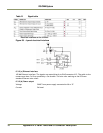
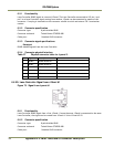
6.2.7 Switches
There are two switches located at the connector:
Table 20 Switch labels
Switch label Switch color
Function
S4 TRIG CAM-0 Push bottom
Generates a trigger pulse to the camera
S3 TRIG POLARITY Slide Selects trigger polarity