


VIS-CAM System
74 Appendix B: J-Panel Functional & Connector Description
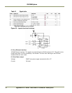
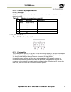
6.5.1 Functionality
Lane Controller RS485 signal to a second J-Panel. The Lane Controller connected to X15 pin 1 and
pin 2 or a Lane Controller signal coming from another J-Panel can be connected by means of this
connector. If no plug is inserted into the connector a build-in switch activates a 120 ? termination
resistor.
6.5.2 Connector specification
Connector type: 8 pole shielded RJ45
Connector on board: Taitek/Kinsun ST3009S-880
Cable part: Standard RJ45 connector
6.5.3 Connector signal specifications
Datasignal
RS485 databus signals from the Lane Controller.
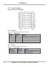
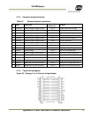
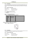
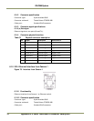
6.5.4 Connector physical Interface
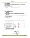
Table 27 Physical connector table for J-panel 2.
Pin Signal Description
Connection to
1 RS485+
RS485 databus D+
2 RS485- RS485 databus D-
3 - NC
4 - NC
5 - NC
6 - NC
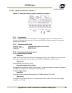
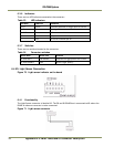
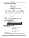
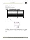
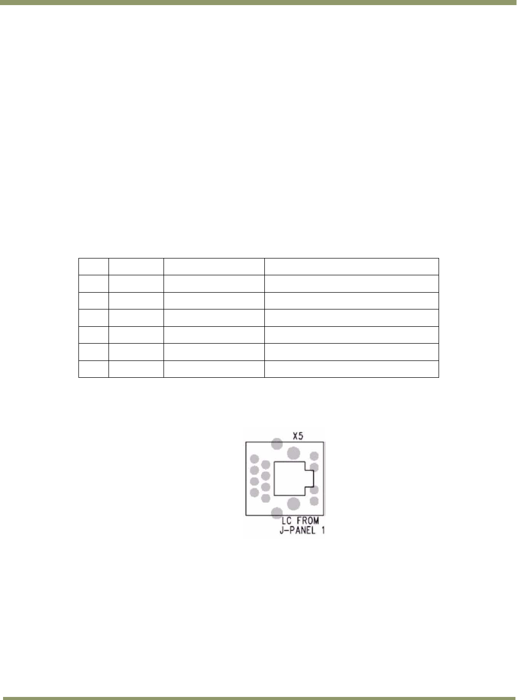
6.6 X5: Lane Controller Signal from J-Panel #1
Figure 73. Signal from J-panel #1
6.6.1 Functionality
Lane Controller RS485 signal from a first J-Panel. If more than one J-Panel is connected to the same
Lane Controller, the signal can be routed from J-Panel #1 X4 to J-Panel #2 X5.
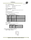
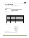
6.6.2 Connector specification
Connector type: 8 pole shielded RJ45
Connector on board: Taitek/Kinsun ST3009S-880
Cable part: Standard RJ45 connector