


VIS-CAM System
6 Preparing for Installation
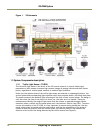
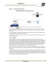
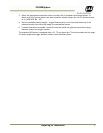
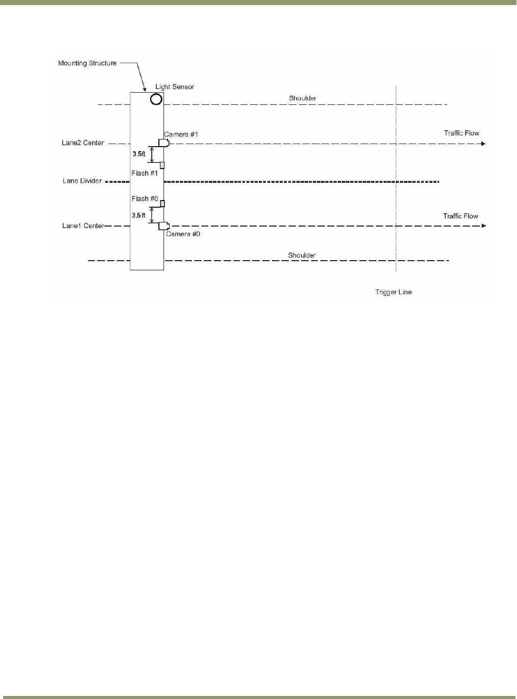
Figure 4. Typical Over Lane Site Layout Plan.
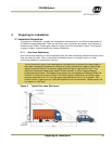
2.1.1 (a) Camera tilt considerations
The requirement to freeze the motion of high-speed vehicles limits how steep or shallow the tilt
angle of the camera may be. For example, it is important to prevent the horizon from appearing in
the image, and thereby allowing the sun to blind the camera. For over lane installations, a camera
tilt between 20° to 30° is recommended–with 25° being considered the optimal angle. This angle of
tilt is the best compromise between minimizing visibility blockages caused by closely spaced
vehicles and maximizing plate visibility for plate mounts that are slightly recessed or tilted
downwards.
2.1.1 (b) Asynchronous triggering considerations
When the VIS is operated in trigger mode, a vehicle detector is employed to cause the camera to
capture an image at the precise moment the vehicle is in the best position to image both the
vehicle and its license plate. The delay between the time the vehicle passes the trigger position on
the road and when the trigger signal actually reaches the VIS must be kept to a minimum to prevent
high-speed vehicles from moving out of the area viewed by the camera before the image is snapped.
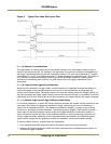
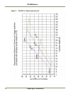
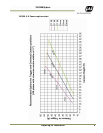
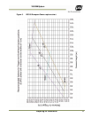
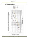
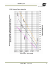
2.1.1 (c) Camera height versus trigger distance considerations
It is critically important, to select the correct distance between the camera and the location on the
road where the camera is triggered to capture an image. Minimizing the cost of installation is
usually also an important concern. This means that whenever possible, it is best to use existing
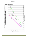
structures or previously installed elements. The following charts (Figure 5 and Figure 6) provide a
wide range of trade-offs between camera height and trigger distance to enable the installer to
select convenient camera and light sensor locations relative to existing mounting structures and
vehicle trigger locations. Adhering to the installation options provided in the installation charts,
yields camera images that are generally suitable for automatic license plate readers (ALPR).
To use the charts correctly, please follow the steps below.
1. First measure the height above the road to convenient camera mounting locations.
2. Measure the distance along the road from directly beneath each candidate camera position to
convenient trigger locations.