


Appendix A: Camera Functional & Connector Description 51
VIS-CAM System
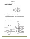
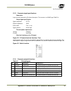
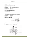
5.3.3 Connector signal specifications
Description
Logic inverter powered by 5V drives the output. The inverter is a HCMOS type 74AHC14.
Output signal specification
Signal amplitude 5V TTL
Output impedance 100 Ω
Pulse width 5 ms ± 1 ms
Signal polarity active high
External power requirement
Voltage 8-26V DC
Current max 25μA
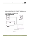
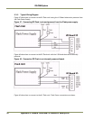
Electrical Interface on the I/O board:
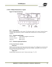
Figure 45. I/O board electrical interface. Test
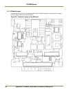
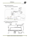
A push button switch S1 can be activated for generation of an output pulse for test purposes. The
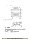
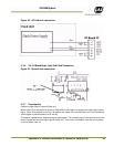
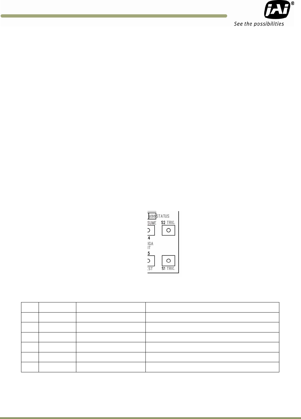
flash output is high as long as the switch is activated. The switch is located as shown on Figure 46:
Figure 46. Switch location.
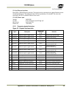
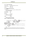
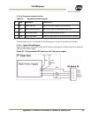
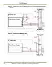
5.3.4 Connector physical Interface
Table 14 Wiring diagram.
Pin Signal Description Connection to
1 I/O Gnd IO Board Gnd
Pin 2 when no power is available from the flash
2 GND Flash Gnd Flash ground (negative power terminal)
3 Out Strobe Out Strobe input on flash unit
4 Stat Strobe status
Status output from flash unit
5 FPW
R
Flash powe
r
Power from flash to output circuit on I/O Board
6 24
V
IO board 24V (Fused 0.5A)
Pin 5 when no power is available from the flash