


List of Figures ix
VIS-CAM System
List of Figures
Figure 1.
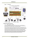
VIS elements ............................................................................................ 2
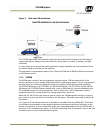
Figure 2. Back shot VIS installation. ............................................................................ 3
Figure 3. Typical Over Lane Site Layout ....................................................................... 5
Figure 4. Typical Over Lane Site Layout Plan. ................................................................ 6
Figure 5. VIS 300 U.S. Camera options chart. ................................................................. 8
Figure 6. VIS 300 European Camera options chart. ......................................................... 11
Figure 7. Typical side of road installation. ................................................................... 14
Figure 8. Typical side of road installation plan view with no canopy/overhead structue. ........... 14
Figure 9. Flash and camera distances. ........................................................................ 15
Figure 10. Install the traffic light sensor. ...................................................................... 17
Figure 11. TLS-300 signal and power cable. ................................................................... 18
Figure 12. Installing the TLS-300 through the mounting pipe and flange. ............................... 18
Figure 13. Pipe clamps should be about 6-inches apart on a vertical surface. ......................... 19
Figure 14. Camera Installation ................................................................................... 19
Figure 15. Camera mount template. ............................................................................ 20
Figure 16. Camera cabling as it appears before electrical installation. .................................. 20
Figure 17. Cable final wiring. .................................................................................... 21
Figure 18. Properly wired X-4 connector. ...................................................................... 22
Figure 19. Back of the video camera. .......................................................................... 22
Figure 20. VIS CAM connections.................................................................................. 24
Figure 21. TLS 300 to J-Panel wiring. ........................................................................... 25
Figure 22. X-6 Power input connection. ........................................................................ 26
Figure 23. Wiring for the X8 to converter connector. ........................................................ 27
Figure 24. Test trigger ............................................................................................ 28
Figure 25. Two lane controller. .................................................................................. 29
Figure 26. TNF-31 flash unit ...................................................................................... 29
Figure 27. S3 switch setting ...................................................................................... 30
Figure 28. Connecting an AC flash. ............................................................................. 30
Figure 29. Connection for LVD to VIS CAM 400. ............................................................... 31
Figure 30. Example of a network connection using a local switch. ........................................ 35
Figure 31. Initial Camera Alignment Display example. ...................................................... 37
Figure 32. Roll Bar Display example. ........................................................................... 38
Figure 33. Readjustment of camera tilt and zoom display. ................................................. 39
Figure 34. Focus Bar marker display. ........................................................................... 40
Figure 35. Focus Bar Waveform display. ....................................................................... 41
Figure 36. Focus Bar Waveform Display with waveform cursors. ........................................... 42
Figure 37. Connection requirements. ........................................................................... 45
Figure 38. Component layout of the EN board. ............................................................... 46
Figure 39. Board connections .................................................................................... 47
Figure 40. Interface drawing. .................................................................................... 48
Figure 41. Electrical interface ................................................................................... 48
Figure 42. Physical interface table. ............................................................................. 49
Figure 43. Category 5 or 6 wiring diagram. .................................................................... 50
Figure 44. Flash connections. .................................................................................... 50
Figure 45. I/O board electrical interface. Test ............................................................... 51
Figure 46. Switch location. ....................................................................................... 51
Figure 47. Connecting DC Flash to a board powered from the Flash power supply. .................... 52
Figure 48. Connection DC Flash to an internally powered board. .......................................... 52
Figure 49. AC flash unit connection. ............................................................................ 53
Figure 50. Second flash connection. ............................................................................ 53
Figure 51. IO board electrical interface. ....................................................................... 54