


Appendix B: J-Panel Functional & Connector Description 75
VIS-CAM System
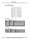
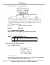
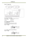
6.6.3 Connector signal specifications
6.6.3 (a) Data signal
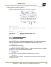
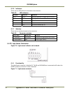
RS485 databus signals from a Lane Controller connected to another J-Panel . 6.6.4 Connector
physical Interface
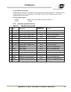
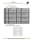
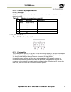
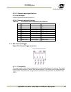
Table 28 Physical pin connections J-panel #1.
Pin Signal Description
Connection to
1 RS485+ RS485 databus D+
2
R
S485- RS485 databus D-
3 - NC
4 - NC
5 - NC
6 - NC
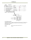
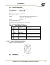
6.7 X6, X7: 24V DC Power
Figure 74. Signal from J-panel #1
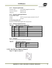
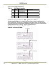
6.7.1 Functionality
The J-Panel has one input for 24V DC (X6). There is one unfused output (X7) and four fused outputs
for Camera 0 (connector X1, fused 2A), Camera 1 (connector X2, fused 2A), Light Sensor (connector
X3, fused 2A) and RS485-to-ethernet Converter (connector X8, fused 300mA).
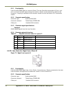
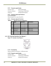
It is possible to reset all fuses and they also reset automatically (PTC type) after removal of
excessive load. The three power LED indicators are electrically located between the fuse and
connector and the status of the fuse is therefore indicated on the LED: when the LED is green the
load is ok, when the LED is red an overload condition is present.