


VIS-CAM System
52 Appendix A: Camera Functional & Connector Description
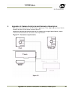
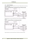
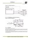
5.3.5 Typical Wiring Diagram
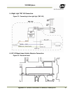
Figure 47 shows how to connect to the DC Flash unit having the I/O Board electronics powered from
the Flash Power Supply.
Figure 47. Connecting DC Flash to a board powered from the Flash power supply.
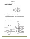
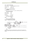
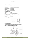
Figure 48 shows how to connect to the DC Flash unit with the I/O Board electronics internally
powered.
Figure 48. Connection DC Flash to an internally powered board.
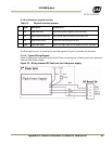
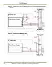
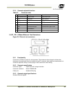
Figure 49 shows how to connect to the AC Flash unit. Flash Power connections not shown.