


Installing the Vehicle Imaging Subsystem 23
VIS-CAM System
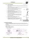
3.3 Installing the J-Panel
The J-panel layout is shown in Appendix A, See “Connection requirements.” on page 43. This
Appendix has a detailed description of the J-Panel function and connectors.
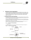
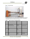
3.3.1 X1 and X2 VIS CAM 300/400
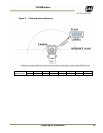
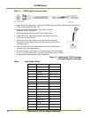
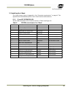
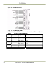
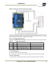
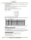
The VIS CAM connections to the J-Panel are shown in Table 3 and Figure 20
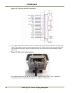
Table 3 VIS CAM connections to the J-Panel.
X1, X2 Pin # Wire Color Signal
Remarks
1 White/orange in Cat5e/6 cable
Ethernet A+
2 Orange in Cat5e/6 cable
Ethernet A-
3 White/green in Cat5e/6 cable
Ethernet B+
4 Green in Cat5e/6 cable
Ethernet B-
5 White/blue in Cat5e/6 cable
Ethernet C+
not used with VIS CAM
6 Blue in Cat5e/6 cable
Ethernet C-
not used with VIS CAM
7 White/brown in Cat5e/6 cable
Ethernet D+
not used with VIS CAM
8 Brown in Cat5e/6 cable
Ethernet D-
not used with VIS CAM
9 Black wire in Red/Black pai
r
Gnd
10 Red wire in Red/Black pai
r
+24V dc
11 White wire in Brown/White pai
r
Vinit+
Trigger signal
12 Brown wire in Brown/White pai
r
Vinit-
Trigger signal
13 White wire in Red/White pai
r
RS485D+
Lane Controlle
r
14 Red wire in Red/White pai
r
RS485D-
Lane Controlle
r
15 White wire in Orange/White pai
r
RS485D+
Lane Controlle
r
16 Orange wire in Orange/White pai
r
RS485D-
Lane Controlle
r