


VIS-CAM System
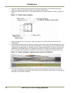
28 Installing the Vehicle Imaging Subsystem
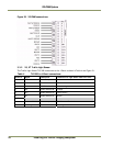
Arrow down – negative going
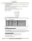
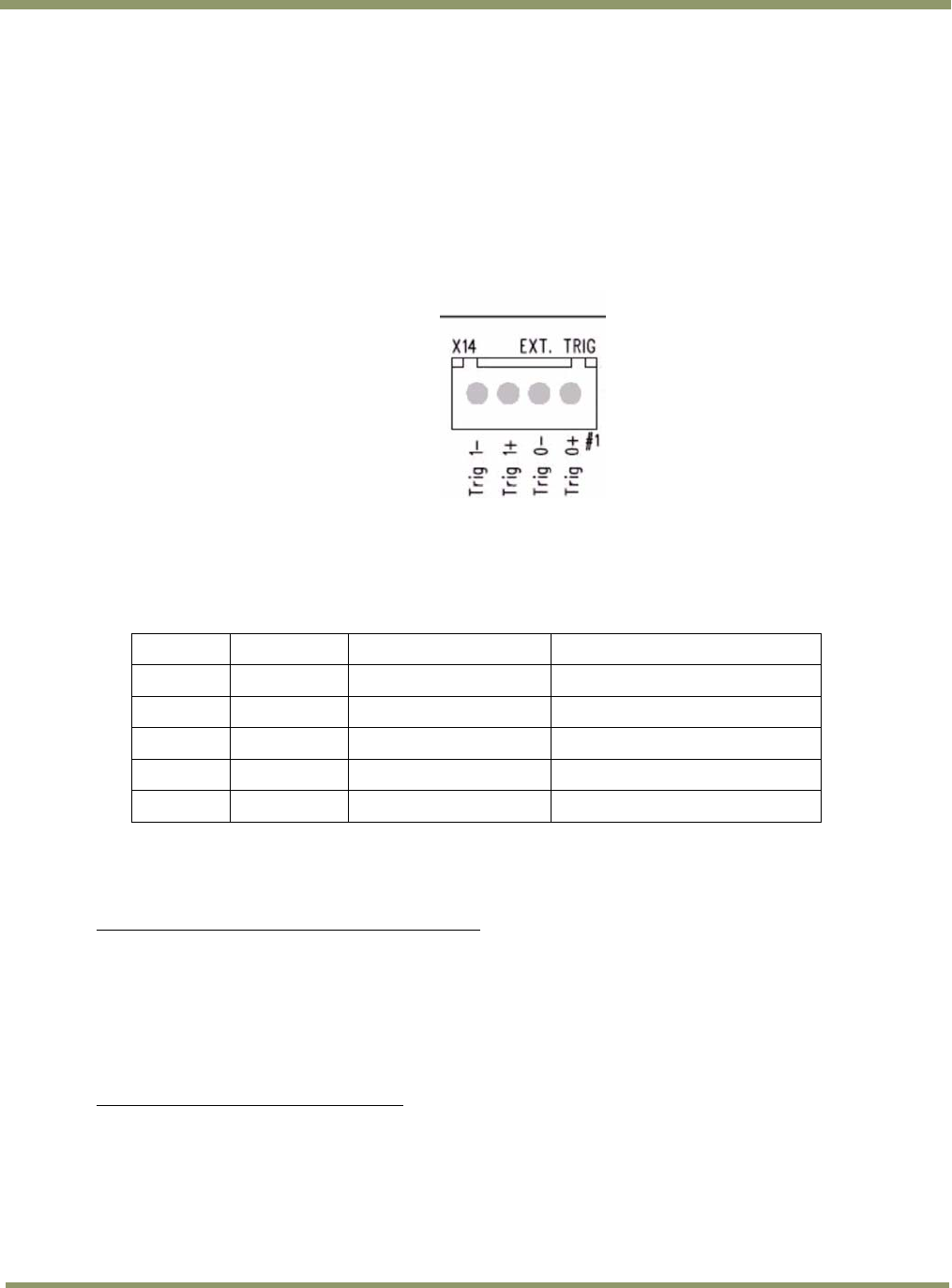
As a guideline the two LEDs marked TRIG-0 and TRIG-1 shall be off when no trigger pulse is present.
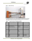
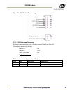
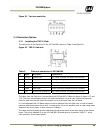
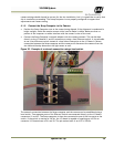
3.3.5 (b) Test Trigger
Activating switches S1 and S4 generates a trigger pulse for test purposes. Only one trigger pulse is
generated each time the switch is activated.
The duration of the trigger pulse is approximately 4 ms.
The trigger indicator LEDs flash when the test trigger switch is activated.
Figure 24. Test trigger
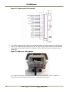
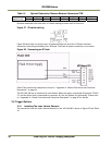
3.3.6 X15 Lane Controller Connector (X4 and X5)
The Lane Controller connection to the J-Panel is connector X15. The connections are listed in Table
8 .
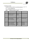
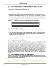
Table 8 X15 Lane Controller
X15 Pin # Signal Description
Connection to
1 D0+ RS485 databus D0+
Lane Controller databus 0+
2 D0- RS485 databus D0-
Lane Controller databus 0-
3 Gnd gnd
gnd
4 D1+ RS485 databus D1+
Lane Controller databus 1+
5 D1- RS485 databus D1-
Lane Controller databus 1-
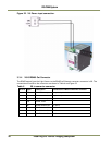
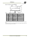
It is possible to have one Lane Controller connected to several cameras or one Lane Controller to
each camera:
One Lane Controller for two or more cameras
1. The Lane Controller is connected to the X15 pin 1 and 2 (no connections to pin 4 and 5)
2. Switch S2 position “OPEN”
3. The Lane Controller can be connected to more J-Panels by connecting RJ45 patch cables between
connector X4 and connector X5 on the next J-Panel (and from X4 on the next J-Panel to X5 on the
third J-Panel). Switch S2 on the other J-Panels must also be in the “OPEN” position.
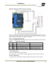
Two Lane Controller to two cameras
1. The Lane Controller for camera 0 is connected to X15 pin 1 and 2
2. The Lane Controller for camera 1 is connected to X15 pin 4 and 5
3. Switch S2 position “TERM”
4. Do not connect any cables to X4 and X5