


18
Getting Started
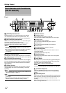
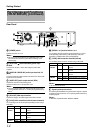
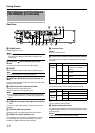
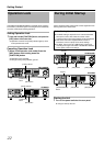
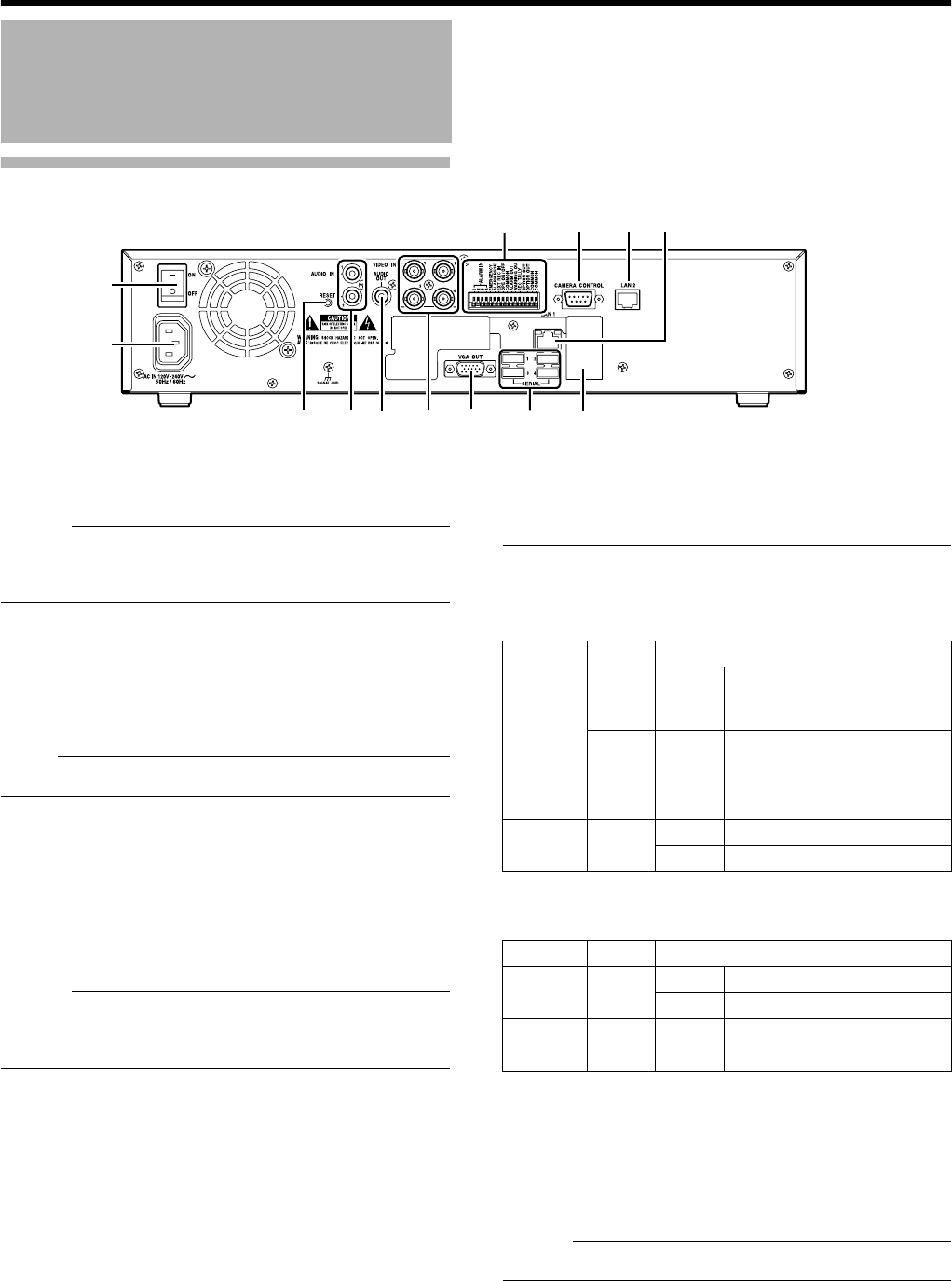
Rear Panel
W
[POWER] switch
Switches the power on or off.
Memo :
●
Be sure to press and hold down the [OPERATE] button on the
front panel to shut down the system before switching off the
power supply.
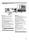
X
[AC IN 120V
H
240VH 50Hz/60Hz] power input
terminal
Connect to an AC outlet using the power cable supplied.
Y
[RESET]
Resets the system. Press this button when a malfunction occurs.
Note :
●
Do not press this button in normal circumstances.
Z
[AUDIO IN 1/AUDIO IN 2] audio input terminals 1/2
(RCA)
Connect to the audio output terminal of the device from which audio
signals are to be recorded.
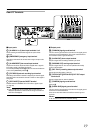
a
[AUDIO OUT] audio output terminal (RCA)
Outputs live sound in the live viewing mode.
Outputs recorded sound in the playback mode.
Memo :
●
There is no audio output when playing back still images, when
running searches other than x1, or when playing back frame-by-
frame.
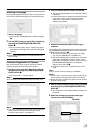
b
[VIDEO IN1 to 4] camera video signal input terminals
1 to 4
Connect to the video output terminal of the analog camera (sold
separately).
c
[VGA OUT] VGA output terminal
Outputs live images, recorded images and the menu screens.
d
[SERIAL1 to 4] serial terminals 1 to 4
For connecting the communication control terminals on a mouse
(sold separately), flash memory (sold separately), UPS (sold
separately) or additional disk drive (sold separately).
e
Connector cover
Memo :
●
Do not remove the cover.
f
[LAN1] LAN1 connection terminal (camera network)
For connecting to the IP camera (sold separately) network using a
LAN cable.
g
[LAN2] LAN2 connection terminal (Intranet)
For connecting to the remote PC network using a LAN cable.
h
[CAMERA CONTROL] camera control terminal
Lets you control the analog cameras.
i
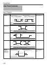
Signal input/output terminals
For operating VR-N1600U/E using external alarm signals or signals
received from external devices, or for operating external devices by
outputting signals.
Memo :
●
Diameter of applicable cable: AWG22 to AWG28
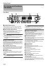
Part Names and Functions
(VR-N900U) (continued)
W
X
cYd
Z
a b
hifg
e
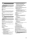
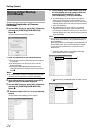
Color Status
Left
Indicator
Off Not connected to the network or
connected to a 10Mbit/Sec
network.
Green On Connected to a 100Mbit/Sec
network.
Orange
On Connected to a 1Gbit/Sec
network.
Right
Indicator
Orange
Off Not communicating.
Blinking Communicating.
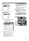
Color Status
Left
Indicator
Green Off Not connected to the network.
Blinking Connected to the network.
Right
Indicator
Green Off Not communicating.
Blinking Communicating.