


26
Preparation
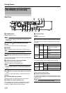
The following operations are possible with this system.
●
Surveillance of up to 16 cameras (VR-N1600U/E)/9 cameras (VR-N900U) (live image, recording and playback)
●
Checking recorded images on the VGA monitor
●
Recording/Playing sound
●
Transmitting audio data to a designated camera (VR-N1600U/E)
●
Alarm recording
●
Remote surveillance using PCs
Memo :
●
Connect LAN1 to the camera network.
●
LAN2 to the surveillance computer network.
●
For details of the protocol and port number for the network cameras
on the LAN1 network, refer to the network camera’s user manual.
●
The protocol and port number used on the LAN2 network are
shown below.
●
Surveillance computer: HTTP 80
●
Mail: SMTP 25, POP 110
●
Time Synchronization: NTP 123
●
Connect NAS to the LAN1 network.
●
Connect the time server to the LAN2 network.
●
Purchasing additional camera licenses enables the VR-N1600U/
E(A) to handle simultaneous recording up to 32 channels.
For details, please consult your nearest JVC dealer.
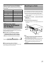
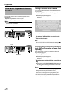
Note :
●
Connect only after having turned
A
OFF
B
the power of all devices.
●
Set the IP address of the camera to 192.168.0.xxx. When setting
the IP address of the camera to an address other than
192.168.0.xxx, you must also change the IP address of LAN1.
Refer to the [Instruction Manual] of each camera for procedures
to change the camera’s IP address,
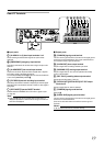
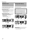
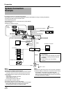
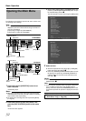
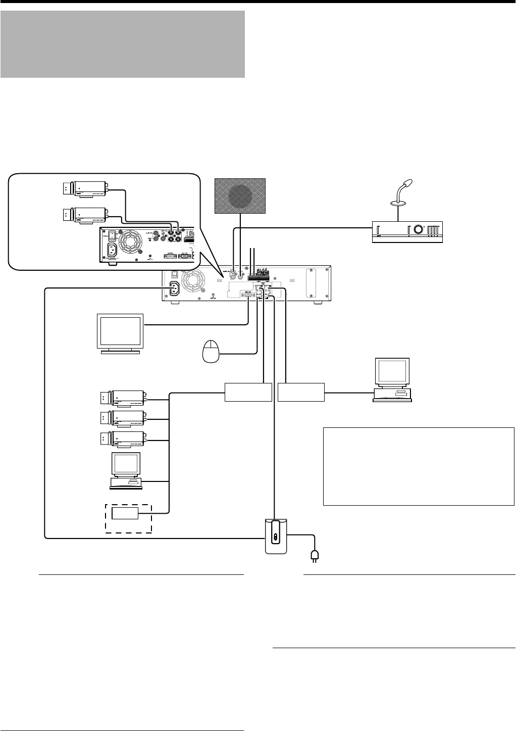
System Connection
Example
ON
OFF
AUDIO IN
AUDIO OUT
ALARM IN/ALARM OUT
VGA OUT
SERIAL
LAN1
LAN2
SERIAL
VR-N900U
VR-N1600U/E
●
You can connect up to 16 cameras.
(VR-N1600U/E)
●
You can connect up to 9 cameras, out of which
a maximum of 4 analog cameras are allowed.
(VR-N900U)
●
You can connect up to 10 surveillance
computers.
Speaker (with built-in amplifier)
ALARM IN/OUT
Supplied power cable
AC 120 H 240 V, 50 Hz/60 Hz
Mic Amp
VGA monitor
IP cameras
Computer for configuring cameras
USB Mouse
Switching
HUB
Switching
HUB
UPS control
UPS
120 V - 240 V
Microphone
Surveillance computer
NAS
Analog
cameras
VIDEO IN 1 to 4