


21
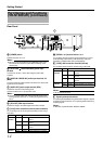
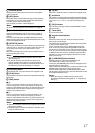
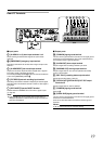
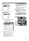
Camera Control Terminal (VR-N900U)
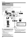
Use connection cables according to the table below. Also make
sure that you read through the instruction manual of the equipment
to be connected.
(D-sub 9 pin, male)
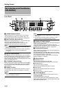
The name of control buttons and operating methods may vary
between VR-N1600U/E and VR-N900U. Such circumstances will
be indicated using the rules below.
Ⅵ When name of control button is different
A
Indicated accordingly using [button name of
VR-N1600U/E] and (button name of VR-N900U)
B
`
mark is inserted at the end of the sentence
Ⅵ When operating method is different
The operation for the respective model is stated, and the model
name is indicated at the end of the sentence.
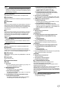
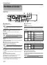
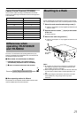
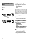
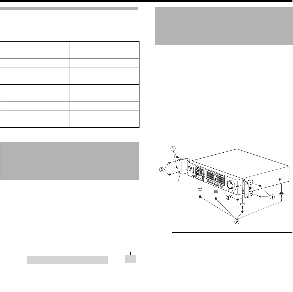
Use the supplied rack mount bracket to mount this unit to the EIA
rack. For the installation to the rack, consult the specialist or dealer.
1 Mount the rack mount bracket using screw (1)
●
Use the 4 screws (M4 x 10 mm) supplied to fasten this unit
at the two sides.
2 Remove the foot screws B (4 pcs) at the bottom
of the unit
●
Remove the foot.
3 Mount to the rack using screws C
●
Use the 4 screws (M5 x 11 mm) supplied to fasten this unit
to the rack.
Note :
●
Do not place any object on this unit when it is mounted to the
rack. Doing so may cause it to lose balance and drop or fall,
hence resulting in injuries or damages.
●
When mounting more than one of this unit to the rack, make sure
to mount each at a distance that is at least equivalent to one
unit.
●
When remounting the removed foot, make sure to use same
screws (M3x6 mm). Using a longer screw may cause
malfunction.
Signal Pin No.
RX+ 1
RX- 2
TX- 3
TX+ 4
GND 5
NC 6
NC 7
NC 8
NC 9
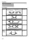
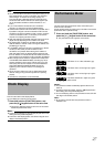
Differences when
operating VR-N1600U/E
and VR-N900U
A
B
Press the [16/ENTER](ZOOM IN/ENTER)button.
Mounting to a Rack
Rack Mount
Bracket
(4 Screws)