


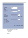
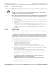

Alarm Task Editor
!
Caution!
Editing scripts on this page overwrites all settings and entries on the other alarm pages. This
procedure cannot be reversed.
In order to edit this page, you must have programming knowledge and be familiar with the
information in the Alarm Task Script Language document.
As an alternative to the alarm settings on the various alarm pages, you can enter your desired
alarm functions in script form here. This will overwrite all settings and entries on the other
alarm pages.
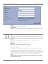
1. Click the Examples link under the Alarm Task Editor field to see some script examples. A
new window will open.
2. Enter new scripts in the Alarm Task Editor field or change existing scripts in line with your
requirements.
3. When you are finished, click the Set button to transmit the scripts to the unit. If the
transfer was successful, the message Script successfully parsed is displayed over the
text field. If it was not successful, an error message will be displayed with further
information.
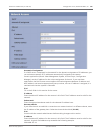
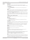
Alarm Rules
The camera features an alarm rule engine. In its simplest form, an alarm rule can define which
input(s) activate which output(s). Basically, an alarm rule allows you to customize the camera
to respond automatically to different alarm inputs.
To configure an alarm rule specify one input from a physical connection, a motion detection
trigger, or from a connection to the camera’s LIVEPAGE. The physical input connection can be
activated by dry contact devices such as pressure pads, door contacts, and similar devices.
Next, specify up to two (2) rule outputs, or the camera’s response to the input. Outputs
include a physical alarm relay, an AUX command, or a preposition scene.
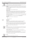
1. Click the Enabled check box to activate the alarm.
2. Choose one of the following alarm Inputs:
Local Input 1: a physical alarm connection.
Local Input 2: a physical alarm connection.
IVA/MOTION+: an alarm when IVA or motion detection is activated.
Connection: an alarm when an attempt is made to access the camera’s IP address.
3. Choose one of the following output commands for both Output 1 and Output 2 settings:
None: no defined command.
Alarm Relay: defines a physical connection from the open collector alarm output.
Aux On: defines a standard or custom keyboard ON command. Refer to User Command
Table, page 158 for a list of valid commands.
Note: Only commands 1, 8, 18, 20, 43, 60, 80, 86 are supported. Support for the
remaining commands is scheduled for a future release.
Aux Off: defines a standard or custom keyboard OFF command. Refer to to User
Command Table, page 158 for a list of valid commands.
Note: Only commands 1, 8, 18, 20, 43, 60, 80, 86 are supported. Support for the
remaining commands is scheduled for a future release.
Shot: defines a preset scene from shot 1-256.
4. Click Set to save and to activate the alarm rules.
14.37
14.38
AutoDome 7000 Series (IP and HD) Configuration via IP, Advanced Mode | en 127
Bosch Security Systems Operation Manual 2013.07 | 1.2.2 | F.01U.283.679