


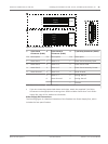
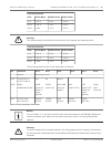
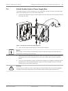


Fuse Specifications
Volts XF101 Mains XF102 Camera XF103 Heater
24 V T 5.0 A T 2.0 A T 3.15 A
115 V T 1.6 A T 2.0 A T 3.15 A
230 V T 0.8A T 2.0 A T 3.15 A
!
Warning!
Fuse replacement by qualified service personnel only. Replace with same type fuse.
Fuse Specifications
Volts XF101 Mains XF102 Camera XF103 Heater
24 V T 5.0 A T 2.0 A T 3.15 A
115 V T 1.6 A T 2.0 A T 3.15 A
230 V T 0.8A T 2.0 A T 3.15 A
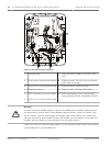
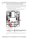
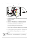
The following table lists the Power Supply Box connectors:
No. Connector Pin 1 Pin 2 Pin 3 Pin 4 Pin 5 Pin 6
Ground Grounding Screw
P101 115/230 VAC or
24 VAC Power In
Line NC Neutral
P106 SERIAL
COMMUNICATIONS
CODE-
(Audio IN-,
Audio in
signal
ground)
CODE+
(Audio IN+)
Earth GND
(Ground)
(Audio)
RXD
(Audio OUT+)
TXD
(Audio OUT-;
Audio out
signal
ground)
Signal
GND
(Ground)
P107 24 VAC Power
(Arm Harness)
Camera
24 VAC
Camera
24 VAC
Earth
Ground
Heater
(24 VAC)
Heater
(24 VAC)
Table 7.1: Power Supply Box Connections
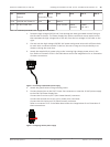
Notice!
Pins for P106 1, 2, 4, and 5 are used for audio input and output for AUTODOME 7000 Series
cameras; however, their labels are still those of previous versions of analog AUTODOME
cameras.
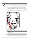
!
Warning!
For units intended to be installed outdoors: All wiring (power and I/O cabling) connecting to
the unit must be routed separately inside different permanently earthed metal conduits (not
supplied).
AutoDome 7000 Series (IP and HD) Installing the Pendant Arm Wall, Corner, and Mast (Pole) Mounts | en 27
Bosch Security Systems Operation Manual 2013.07 | 1.2.2 | F.01U.283.679