


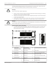
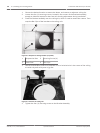
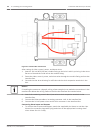
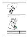

Figure 9.6: Interface Box Connections
After routing all video, control, power, and alarm wires:
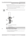
1. Attach a 3/4-inch NPS (20-mm) conduit fitting to the hole in which you bring in the wires.
Be sure to thread the inside nut to the conduit fitting.
2. Route the video, control, power, and alarm wires through the conduit fitting and into the
Interface Box.
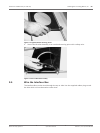
3. Cut and trim the wires allowing for sufficient slack to their respective terminals in the
box.
Notice!
If installing the camera to a drywall ceiling, allow enough wire to make the connections in the
Interface Box below the ceiling. Refer to the Wire the Interface Box section below.
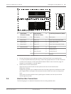
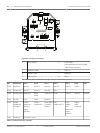
4. Attach the remaining control data in/out wires to their respective terminals in the
Interface Box.
5. Connect the Ethernet cable to its mating connector J101 in the Interface Box.
6. Connect the 24 VAC power wires to the P101 connector in the Interface Box.
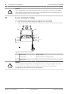
Connecting Alarm Inputs and Outputs
4 To connect alarm inputs and outputs, attach the supplied 6-pin Alarms In and the 4-pin
Alarms Out connector plugs with flying lead wires to the appropriate incoming alarm
wires. Alarm Out 4 is a relay.
60 en | Installing the In-Ceiling Mount AutoDome 7000 Series (IP and HD)
2013.07 | 1.2.2 | F.01U.283.679 Operation Manual Bosch Security Systems