


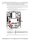
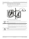
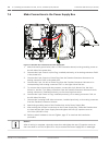


Route Power through Intermediate Power Supply Box
You may route the main power supply through a VG4-PSU1 (120 V transformer) or through a
VG4-PSU2 (230 V transformer) Power Supply Box before connecting the power to a VG4-PA0
(24 V, no transformer) Power Supply Box. The main issue with this configuration is that the 5-
pin power out connector from the VG4-PSU1 or VG4-PSU2 does not match to the 3-pin power
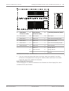
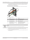
input of the VG4-PA0 power supply. The illustration below depicts:
– A VG4-PSU1/VG4-PSU2 Power Supply Box.
– The main power supply connected to the P101 connector and to the grounding screw.
– The 24 VAC power out wire connected to the P107 heater power connectors.
GND
T
XD
R
XD
C+
C-
GND
T
XD
R
XD
C+
C-
P101
1 2 3
6 5 4 3 2 1
6 5 4 3 2 1
6 5 4 3 2 1
6 5 4 3 2 1
6 5 4 3 2 1
6 5 4 3 2 1
6 5 4 3 2 1
6 5 4 3 2 1
6 5 4 3 2 1
6 5 4 3 2 1
6 5 4 3 2 1
6 5 4 3 2 1
6 5 4 3 2 1
6 5 4 3 2 1
6 5 4 3 2 1
6 5 4 3 2 1
6 5 4 3 2 1
6 5 4 3 2 1
6 5 4 3 2 1
P106
P105
P107
XF102 XF103
XF101
5 4 3 2 1
J103
J103
J103
J102
J101
(LED)
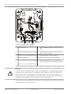
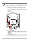
VG4-PSU1 / VG4-PSU2
HTR DOME
(FUSE)
(FUSE)
(FUSE)
(FUSE)
LINE NC NEUT
Figure 7.3: VG4-PSU1/VG4-PSU2
1
120/230 VAC Power In 5 Transformer
2 Ground Wire 6 In/Out Conduit (1/2 in. [15 mm] NPS Fitting
3 P101 Connector 7 24 VAC Power Out to VG4-PA0
4 P107 Connector
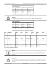
To properly wire the incoming high voltage and the outgoing low voltage lines, refer to this
table:
7.3
28 en | Installing the Pendant Arm Wall, Corner, and Mast (Pole) Mounts AutoDome 7000 Series (IP and HD)
2013.07 | 1.2.2 | F.01U.283.679 Operation Manual Bosch Security Systems