


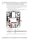

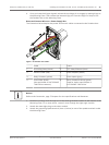
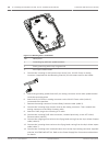
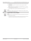
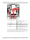

Figure 7.11: Mounting Plate - Inside Detail
Ref.
Description
1 Grounding lug with two spade terminals
2 Earth ground lug with crimp ring terminal
3 Wire input conduit holes
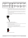
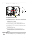
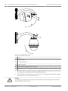
4. Connect the incoming 24 VAC power wires to the 5-pin, 24 VAC Power In mating
connector (supplied with the Mounting Plate kit) for the camera and for the Heater.
5. Attach the grounding spade from the 5-pin mating connector to the other spade terminal
inside the mounting plate.
6. Attach the 5-pin Power In mating connector to the 24 VAC Power cable (cable 2)
connected to the pendant.
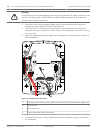
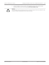
7. Remove the mating connector from the Relay Contacts cable (cable 3).
8. Connect the incoming relay contact wires to the mating connector. Then, reattach the
mating connector to the Relay Contacts cable.
9. Attach an RJ45 plug to the incoming UTP cable.
10. Connect the incoming RJ45 video connector, installed previously, to the UTP Video/
Ethernet cable (cable 5).
11. Connect the outgoing alarm wires to the flying leads coming from the 4-pin Alarm Outputs
cable (cable 6).
12. Connect the incoming alarms wires to the flying leads coming from the 6-pin Alarm Inputs
cable (cable 7).
13. Connect the incoming serial communication wires to the 6-pin mating connector supplied
with the VGA-PEND-WPLATE kit. Refer to the Power Supply Box Connections table above
for details.
36
en | Installing the Pendant Arm Wall, Corner, and Mast (Pole) Mounts AutoDome 7000 Series (IP and HD)
2013.07 | 1.2.2 | F.01U.283.679 Operation Manual Bosch Security Systems