


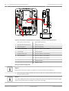
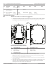
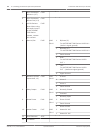

No. Connector Pin 1 Pin 2 Pin 3 Pin 4 Pin 5 Pin 6
Ground Grounding Screw
P101 115/230 VAC or
24 VAC Power In
Line NC Neutral
P107 24 VAC Power to
Dome Plug
Dome
24 VAC
Dome
24 VAC
Earth Ground Heater
(24 VAC)
Heater
(24 VAC)
Table 8.1: Power Box Connections
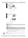
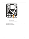
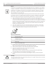
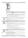
Attach Cover Door to Power Supply Box
1. Compress the bottom hinge pin by pushing the pin lever down and then rotate it behind
the Hinge Pin Stop. The power box Cover Door provides a Hinge Pin Stop to hold the
bottom hinge open while attaching the door.
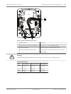
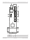
GND T XD R XD C+ C- GND T XD R XD C+ C-
(FUSE)
(FUSE)
(FUSE)
90
o
HTR DOME
LINE NC NEUT
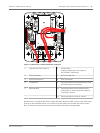
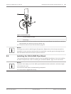
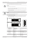
Figure 8.5: Align Cover Door Hinge to Power Box
1
Power Supply Box 5 Hold Hinge Pin Open
2 Cover Door 6 Open Position
3 Align Top Hinge 7 Hinge Pin Stop
4 Align Bottom Hinge
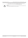
2. Open the top hinge by pushing its pin lever outward and holding it open.
Note: Both Hinge Pins must be fully compressed to open (unlock) the female hinges of
the Cover Door before proceeding to the next step.
3. While holding the top hinge pin open, position the Cover Door to the Power Supply Box
and align its hinges.
4. When the hinges are aligned, release the top hinge pin to engage its mating hinge on the
power box. Then release the bottom hinge pin from the Hinge Pin Stop to complete
attaching the Cover Door to the Power Supply Box.
8.3
46 en | Installing the Roof Parapet and Pipe Mounts AutoDome 7000 Series (IP and HD)
2013.07 | 1.2.2 | F.01U.283.679 Operation Manual Bosch Security Systems