


TRANSFORMER
(115/230VAC
MODELS)
P101
1 2 3
6 5 4 3 2 1 6 5 4 3 2 1
P106
XF102 XF103
XF101
J103
J103
J103
J103
J102
J102
J102
J102
J101
J101
J101
J101
J101
J101
J101
J101
J101
J101
J101
J101
J101
J101
J101
J101
J101
J101
J101
J101
J101
J101
J101
J101
J101
J101
J101
J101
J101
J101
J101
J101
J101
J101
J101
J101
J101
J101
J101
J101
J101
J101
J101
(LED)
P107
5 4 3 2 1
GND TXD RXD C+ C-
P105
GND TXD RXD C+ C-
HTR DOME
a
(FUSE)
(FUSE)
(FUSE)
(FUSE)
(FUSE)
(FUSE)
(FUSE)
(FUSE)
(FUSE)
(FUSE)
(FUSE)
(FUSE)
(FUSE)
(FUSE)
(FUSE)
(FUSE)
(FUSE)
(FUSE)
(FUSE)
(FUSE)
LINE NC NEUT
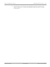
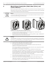
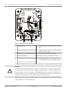
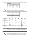
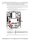
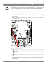
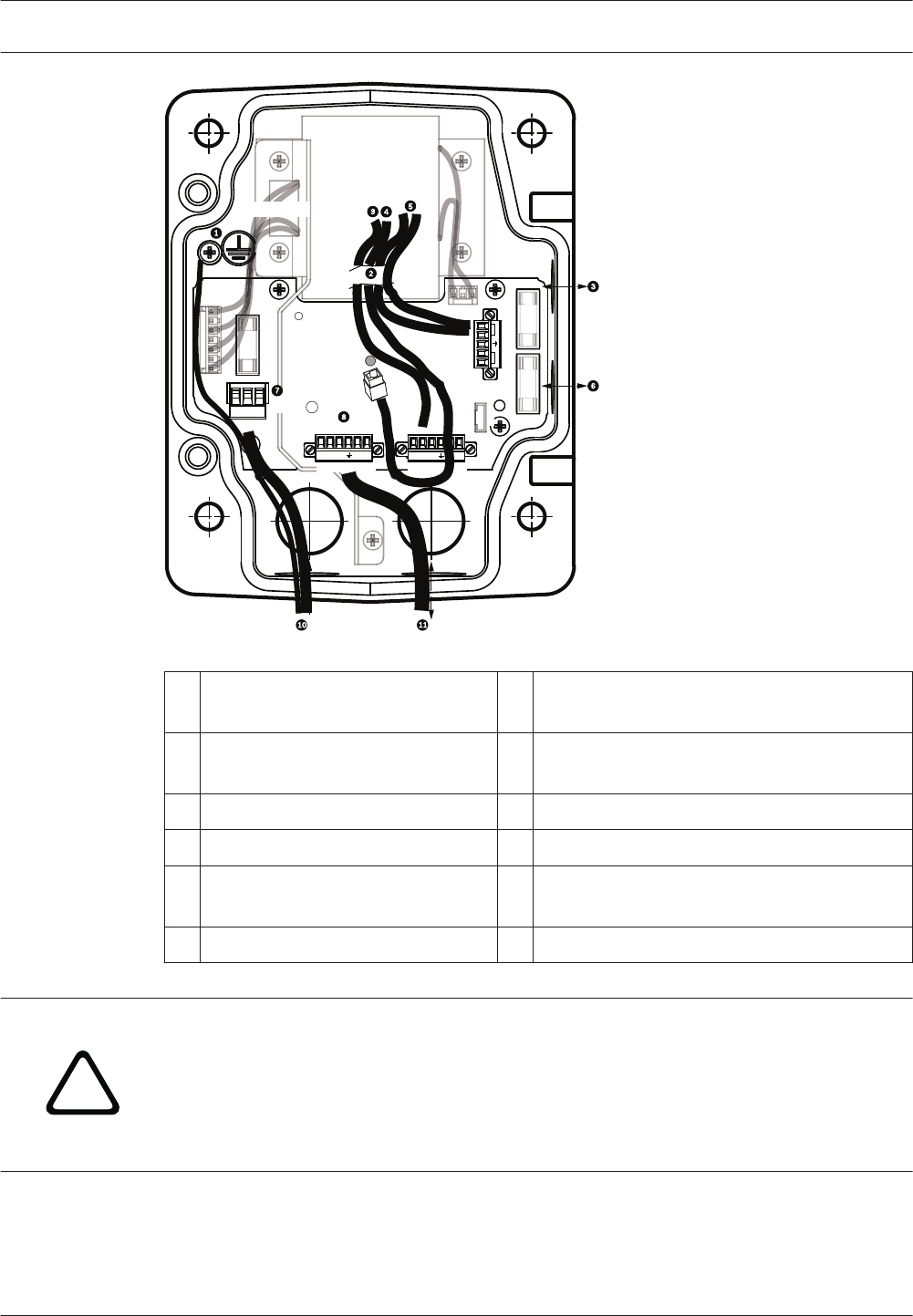
Figure 7.2: Pendant arm power supply box
1
Ground Screw 7 P101 Connector; Power In (120 VAC / 220
VAC)
2 From Harness (Nexus cable bundle) 8 P106 Connector; Control In/Out for external
audio input and output
3 In/Out; 1/2 in. (15 mm) NPS Fitting 9 P105 Connector; Audio to camera
4 Ethernet connector 10 Power In; 3/4 in. (20 mm) NPS Fitting
5 P107 Connector; 24 VAC to camera 11 Audio Input/Output; 3/4 in. (20 mm) NPS
Fitting (labeled “SERIAL COMMUNICATIONS”)
6 In/Out; 1/2 in. (15 mm) NPS Fitting
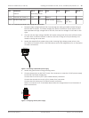
!
Warning!
In earlier Bosch AUTODOME cameras, cable 8 in the ARM mount is labeled “Control In/Out”
and was used for external RxD/TxD and Biphase communications. In the AUTODOME 7000
Series cameras: If you are mounting an AUTODOME 7000 Series camera to an ARM mount
that was wired for an earlier model of Bosch AUTODOME, you must either re-wire cable 8 to
be audio input and output, or disconnected it from the power supply.
Cables/wires that are routed through number 2 in the illustration above come from the Nexus
cable bundle that is in the pendant Arm.
26 en | Installing the Pendant Arm Wall, Corner, and Mast (Pole) Mounts AutoDome 7000 Series (IP and HD)
2013.07 | 1.2.2 | F.01U.283.679 Operation Manual Bosch Security Systems