


1. This function is also accessible by using the mouse scroll wheel while in the Live video
frame.
2. This button is also used as the “Enter” button to select menu items from the AUX tab.
To control a peripheral, follow these steps:
1. Click the appropriate controls.
2. Move the mouse cursor over the video image. Additional options for controlling
peripherals are displayed with the mouse cursor.
3. To manually pan throughout the image area, move your cursor over any part of the live
video. The image area displays a directional arrow (
), then click and hold
the right mouse key to pan the camera.
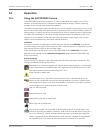
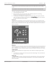
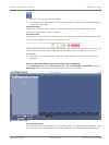
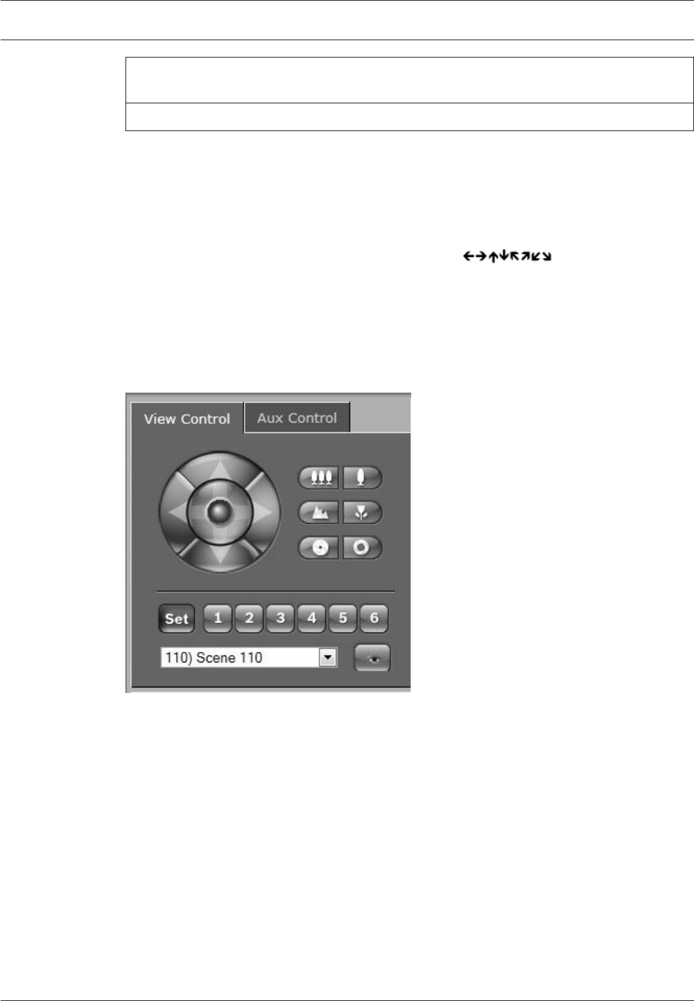
Preset List
The View Control Tab displays a list of all presets with their titles, if any are defined, below
Presets 1-6. To move the camera to a preset shot, select the appropriate preset from the drop-
down list. Refer to Prepositions and Tours, page 106 to define a preset scene and to specify a
title for the preset.
Figure 15.1: View control tab preset / scene list
Digital I/O
The alarm icon is for information purposes and indicates the status of an alarm input: When an
alarm is triggered, the icon lights up blue. The device’s configuration determines whether the
alarm is displayed, as well as additional details (see the AUTODOME 7000 Series online help).
Triggering Relay
You can switch connected units using the relays in the camera (for example, lights or door
openers).
4 To activate this, click the icon for the relay next to the video image. The icon will be red
when the relay is activated.
System Log
The System Log field contains information about the operating status of the camera and the
connection. You can save these messages automatically in a file (see the AUTODOME 7000
Series online help).
AutoDome 7000 Series (IP and HD)
Operation | en 141
Bosch Security Systems Operation Manual 2013.07 | 1.2.2 | F.01U.283.679