


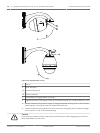
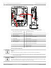
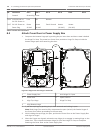
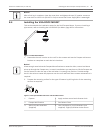

1. Cut and trim the high voltage 115/230 VAC power and ground wires with sufficient slack
to reach their connector terminal in the box, but not so long as to be pinched by or to
obstruct closing the Cover Door.
2. Attach the supplied 3-pin Power Plug to the incoming high voltage power wires in the
box. Refer to connector P101 in the Power Supply Box Connections section below.
3. Route the Ethernet cable out to where the camera will be mounted.
4. Route the low power 24 VAC wires from the right side of the Power Supply Box out to
where the camera will be mounted. Attach the supplied 5-pin 24 VAC Dome plug to the
wire ends inside the box. Refer to connector P107 in the Power Supply Box Connections
section below.
Notice!
All video, control, and alarm wires either pass through the Power Supply Box or by-pass it and
connect directly to the Pipe Interface Board.
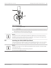
Wiring the Fiber Optic Model
If installing a Fiber Optic model, follow these steps:
Notice!
Refer to the Connection, page 70 chapter for fiber optic specifications.
For instructions on installing a fiber optic module into a power supply box, see the VG4 Fiber
Optic Media Converter Installation Guide that ships with the module.
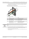
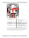
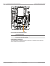
1. Bring the fiber optic cable (item 3 in the figure below) into the right side of the power
supply box.
2. Connect the fiber optic cable to the port for the SFP module (item 2 in the figure below).
3. Connect the RJ45 plug of the cable to the RJ45 socket (item 1 in the figure below) on the
fiber optic module in the power supply box.
4. Route the control wires from the Power Supply to the Pipe Interface Board. Then attach
the supplied six (6) pin control data connector to the wires in the Power Supply Box.
Refer to Wire the Pipe Interface Board, page 50.
AutoDome 7000 Series (IP and HD) Installing the Roof Parapet and Pipe Mounts | en 43
Bosch Security Systems Operation Manual 2013.07 | 1.2.2 | F.01U.283.679