


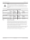

Wire Specifications
Wire Type Shielded Coax (recommended)
Distance Typically 10 m (33 ft), but depends on the signal level
Gage Typically 22 AWG to connector (P105/P106), but depends on the style of connector used
Shield Bare copper braid: 95% coverage
Center
conductor
Stranded bare copper
Note that long distances are more susceptible to introducing noise into the signal.
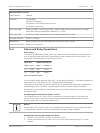
Audio Line Level Input Connections
1. Remove the 100 Ohm termination resistor from the C+ to C- terminals.
2. Connect the audio line level source to the Audio_In+ (C+) input terminal.
3. Connect the audio signal ground to the Audio_In- (C-) input terminal.
Audio Line Level Output Connections
1. Connect the audio line level input of the audio output device (for example, an amplified
speaker or a PC line level input) to the Audio_Out+ (RXD) output terminal.
2. Connect the audio line level output signal ground to the Audio_Out- (TXD) output
terminal.
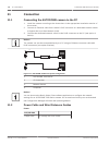
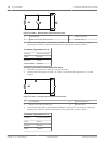
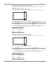
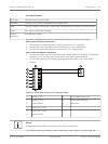
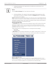
Figure 11.6: Connections for audio over an Ethernet network
1
Audio_In- (C-) 7 AUTODOME Data In/Out
2 Audio_In+ (C+) 8 P105/P106 Connector
3 Earth Ground 9 Audio Out
4 Audio_Out+ (RXD)
5 Audio_Out– (TXD)
6 Signal Ground
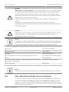
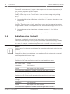
Notice!
Separate the audio cables from the AC power lines to avoid noise.
To configure audio on the camera, refer to Basic Mode: Audio, page 87 or Audio, page 108.
AutoDome 7000 Series (IP and HD) Connection | en 77
Bosch Security Systems Operation Manual 2013.07 | 1.2.2 | F.01U.283.679