


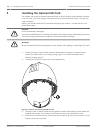
Installing the Pendant Arm Wall, Corner, and Mast
(Pole) Mounts
Description
This chapter details how to install an AUTODOME to a Wall, Corner, or Mast (pole) mount. Any
differences to the installation between these two mounting systems are noted.
Route Wires and Attach Connectors
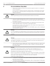
Notice!
If you plan to route the power through an intermediate power supply box, refer to Route
Power through Intermediate Power Supply Box, page 28.
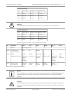
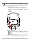
Power wires must be routed to the left (front) side of the Power Supply Box through a
separate electrically earth-grounded conduit. All video, control, and alarm wires must be
routed through a second electrically earth-grounded conduit to the right side of the box.
!
Warning!
External interconnecting cables are to be installed in accordance to NEC, ANSI/NFPA70 (for
US application) and Canadian Electrical Code, Part I, CSA C22.1 (for CAN application) and in
accordance to local country codes for all other countries.
Branch circuit protection incorporating a 20 A, 2-pole Listed Circuit Breaker or Branch Rated
Fuses are required as part of the building installation. A readily accessible 2-pole disconnect
device with a contact separation of at least 3 mm (0.12 in.) must be incorporated.
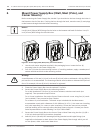
Making the Connections
Notice!
Refer to the Connection, page 70 chapter for wire specifications and distances.
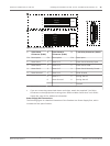
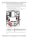
1. Route all video, control, and alarm wires through the earth-grounded conduit fitting on
the right side of the power box.
2. Route the high voltage 115/230 VAC lines through the earth-grounded conduit fitting on
the left side of the box. The Power Supply Box with a transformer comes with a barrier
that separates the high voltage side on the left, from the low voltage 24 VAC side on the
right.
3. Cut and trim all wires with sufficient slack to reach their connector terminals in the box,
but not so long as to be pinched by or to obstruct closing the Pendant Arm. Refer to the
image above for the connector locations.
4. Attach the supplied 3-pin Power Plug to the incoming power wires. Refer to connector
P101 for wire connections.
5. If audio input and/or audio output is required, attach the supplied 6-pin SERIAL
COMMUNICATIONS to P106 in the Power Supply Box. Refer to connector P106 in the
Power Supply Box Connections section below.
6. Attach an RJ45 plug to the incoming Ethernet cable.
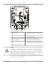
Connecting Alarm Inputs and Outputs
4 To connect alarm inputs and outputs, attach the supplied 6-pin Alarms In and the 4-pin
Alarms Out connector plugs with flying lead wires to the appropriate incoming alarm
wires. Alarm Out 4 is a relay.
7
7.1
7.2
24 en | Installing the Pendant Arm Wall, Corner, and Mast (Pole) Mounts AutoDome 7000 Series (IP and HD)
2013.07 | 1.2.2 | F.01U.283.679 Operation Manual Bosch Security Systems