


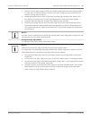
Notice!
After all wiring is complete, close the cover door and tighten the two (2) captive screws on
the cover door to 10-12 N-m (90-105 in.-lbs) to ensure the Power Supply Box is watertight.
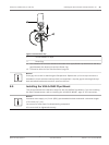
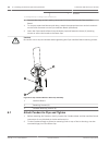
Installing the VGA-ROOF-MOUNT
This section details the installation steps for the Roof Parapet Mount. If you are installing a
pipe mount, refer to Installing the VG4-A-9543 Pipe Mount, page 49 for instructions.
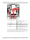
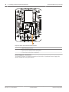
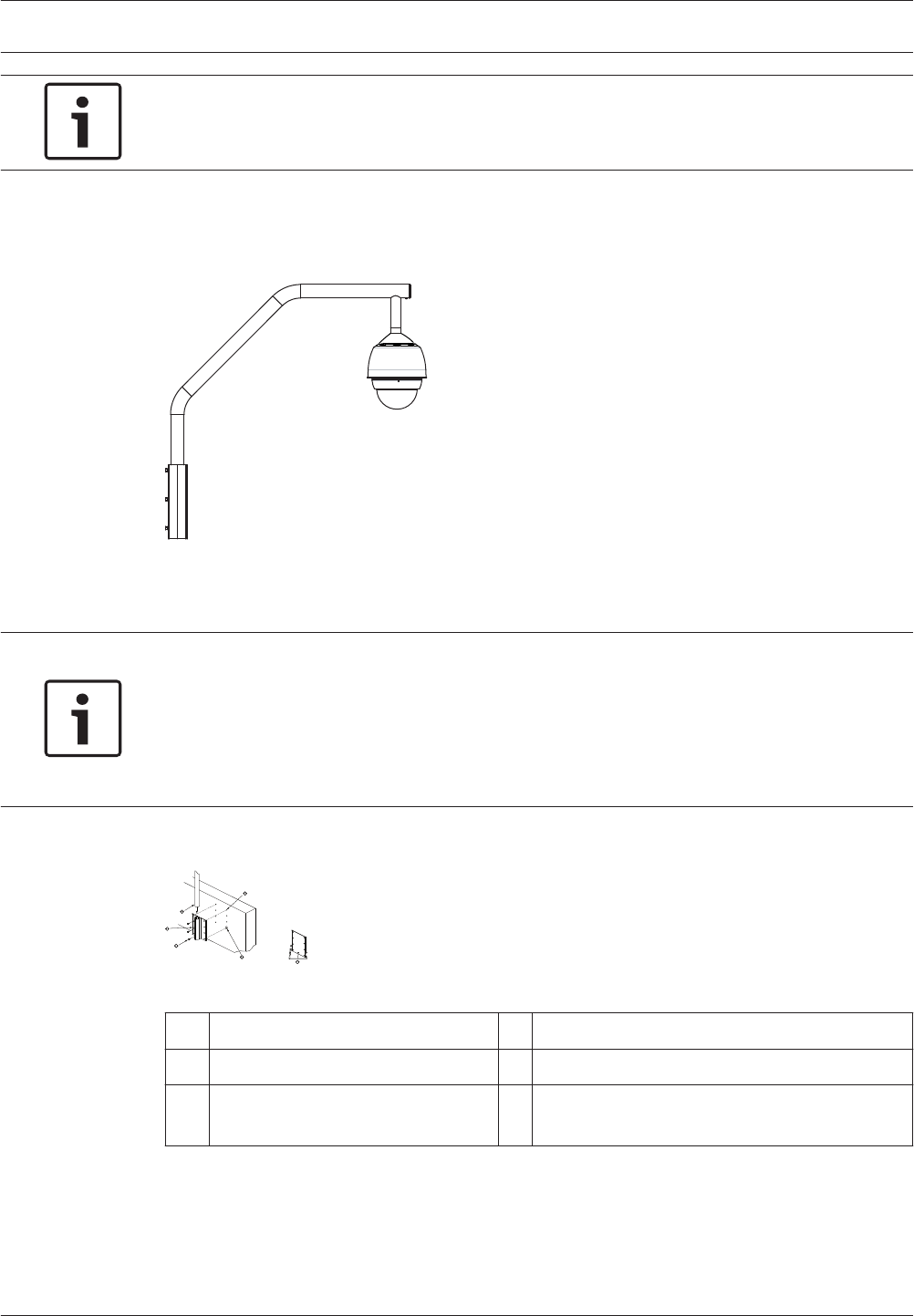
Figure 8.6: VGA-ROOF-MOUNT
1. Determine the wall location on the roof for the camera and use the Parapet wall mount
bracket as a template to mark the hole locations.
Notice!
Allow enough room below the Parapet Mount Bracket to route the video, control and alarm
wires up through the Parapet arm. In certain installations you may have to lift the Parapet arm
for the camera to clear the top of the wall when it is swung into position. Provide enough
slack in the wires to rotate the pipe arm over the roof and back when camera maintenance is
required.
2. Prepare the mounting surface for the type of fastener by drilling holes for the mounting
anchors as required.
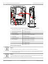
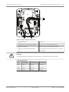
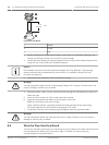
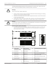
Figure 8.7: Parapet Wall Mount Bracket and Roof Mount Plate
1 Pipearm 4 Apply sealant around each fastener hole
2 Parapet Wall Bracket 5 Roof Mount Plate
3 3/8-16 SS Hex Head Bolt
(supplied)
6 Use a minimum of six (6) fasteners (not
supplied). Eight (8) fastener holes shown.
8.4
AutoDome 7000 Series (IP and HD) Installing the Roof Parapet and Pipe Mounts | en 47
Bosch Security Systems Operation Manual 2013.07 | 1.2.2 | F.01U.283.679