


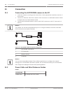

Ethernet Media Converter
Data Interface Ethernet
Data Rate 10/100 Mbps
IEEE 802.3 Compliant
Full Duplex or Half Duplex Electrical Port
Full Duplex Optical Port
Fiber Type, MMF 50/125 µm MMF. For 50/125 µm fiber, subtract 4 dB from the specified optical budget
value. Must meet or exceed fiber standard ITU-T G.651.
Fiber Type, SMF 8–10/125 µm SMF. Must meet or exceed fiber standard ITU-T G.652.
Maximum Distance 20 km (12.4 miles)
Requirement Media converter receiver (CNFE2MC/IN) at controller end of system
Terminal Connection Duplex LC or Single SC
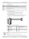
Alarms and Relay Connections
Alarm Inputs
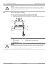
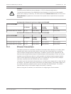
The camera provides seven alarm inputs. Each input can be activated by dry contact devices
such as pressure pads, passive infra-red detectors, door contacts, and similar devices. The
table below summarizes the size and distance wires.
Wire Size Maximum Distance
AWG mm feet meters
22 0.644 500 152.4
18 1.024 800 243.8
Table 11.1: Alarm wire guide
You wire alarms either Normally Open (N.O.) or Normally Closed (N.C.), and must program the
alarm inputs N.O. (the default) or N.C. through the SETTINGS page.
The camera incorporates two types of alarms: Non-supervised and Supervised. In addition to
transmitting an alarm condition, a supervised alarm also transmits a tamper condition.
Depending on how the alarm is configured, a short or a break in the alarm’s circuit can trigger
the tamper signal.
Configuring Supervised Alarms (inputs 1 and 2)
To configure Alarm 1 or 2 (pin 5 or 6) for supervision, you must install a 2.2 K end-of-line
resistor in the circuit. Then, you program the alarms through the Settings menu to either
Normally Open (N.O.) or Normally Closed (N.C.).
Notice!
Only Alarms 1 and 2 (pins 5 or 6) can be configured for supervision. Once a supervised alarm
is programmed it does not need to be enabled to indicate a tamper condition.
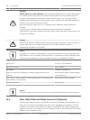
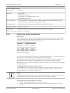
Configuring a Normally Open Supervised Alarm
1. Install a 2.2 K end-of-line resistor in the alarm circuit.
2. Connect the alarm wires to input 1 or 2 (pin 5 or 6) and to the ground (pin 7) at the
camera.
11.5
AutoDome 7000 Series (IP and HD) Connection | en 73
Bosch Security Systems Operation Manual 2013.07 | 1.2.2 | F.01U.283.679