


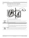

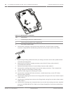

4. Once you have the hinges aligned, release the top hinge pin to engage its mating hinge on
the Mounting Plate. Then release the bottom hinge pin from the Hinge Pin Stop to lock
the Pendant Arm to the Mounting Plate.
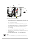
Route and Connect Wires to a Power Supply Box
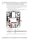
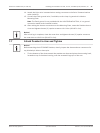
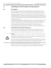
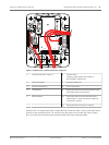
The illustration below depicts the power and control cables connected to the Pendant Arm:
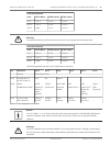
Figure 7.10: Pendant Arm Cables
Cable Cable
1 Grounding Strap (black) 5 UTP Video/Ethernet (blue)
2 24 VAC Power (red) 6 Alarm Outputs (white)
3 Relay Contacts (yellow) 7 Alarm Inputs (gray)
4 Coax Video (black)
(Not applicable for AUTODOME
7000 Series cameras)
8 Serial Communications (green)
Used for Audio Input/Output in
AUTODOME 7000 Series.
Notice!
Refer to the Connection, page 70 chapter for wire specifications and distances.
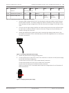
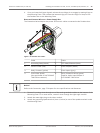
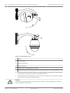
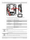
1. Route all incoming wires through one of the earth-grounded conduits at the bottom of the
Mounting Plate. For a mast mount, route all wires through the right-angle conduit.
2. Attach the water-tight plug to the other conduit.
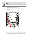
3. Attach the grounding spade terminal (item 1, below) to one of the spade terminals inside
the Mounting Plate.
AutoDome 7000 Series (IP and HD) Installing the Pendant Arm Wall, Corner, and Mast (Pole) Mounts | en 35
Bosch Security Systems Operation Manual 2013.07 | 1.2.2 | F.01U.283.679