


Make Connections in the Power Supply Box
1 2 3
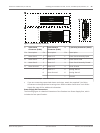
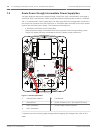
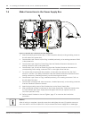
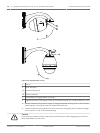
Figure 7.8: Pendant Arm connections to Power Supply Box
1. Attach the earth ground wire (item 1 in the illustration above) to the grounding screw on
the left side of the power box.
2. Connect the 6-pin Control In/Out Plug, installed previously, to its mating connector P106
in the power box.
3. Connect the 6-pin Control to Dome Plug from the Pendant Connector Harness to its
mating connector P105 in the power box.
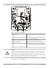
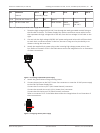
4. Connect the 5-pin, 24 VAC to Dome Plug from the Pendant Connector Harness to its
corresponding color mating connector P107 on the right side of the box.
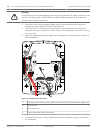
5. To connect alarm inputs and relay outputs, connect the 4-pin Alarms Out, the 6-pin
Alarms In, and the 7-pin Relay connectors from the Pendant Connector Harness to their
mating connectors, installed previously, to the incoming alarm wires.
6. Connect the 3-pin Power In Plug, installed previously, to its mating connector P101 on
the left side of the box.
7. Connect the incoming RJ45 video connector, installed previously, to its mating connector
from the Pendant Connector Harness.
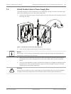
8. Attach the grounding strap of the Pendant Arm to the Power Supply Box.
9. After making the harness connections to the Power Supply Box, rotate the Pendant Arm
to close and seal the Power Supply Box and tighten the two (2) captive screws to
10‑12 N-m (90-105 in.-lbs).
10. Refer to Attach Pendant to Arm and Tighten, page 37 to continue the installation
procedure.
Notice!
After all wiring is complete, close the cover door and tighten the two (2) captive screws on
the cover door to 10-12 N-m (90-105 in.-lbs) to ensure the Power Supply Box is watertight.
7.5
32 en | Installing the Pendant Arm Wall, Corner, and Mast (Pole) Mounts AutoDome 7000 Series (IP and HD)
2013.07 | 1.2.2 | F.01U.283.679 Operation Manual Bosch Security Systems