


GND TXD RXD C+ C-GND TXD RXD C+ C-
P101
P106 P105
P107
XF102 XF103
XF101
5 4 3 2 1
J103
J103
J103
J102
J101
(LED)
HTR DOME
(FUSE)
(FUSE)
(FUSE)
(FUSE)
BNC
J102
P107 P101
P102
P103
P104
P106
J101
AGND
A7
A6
A5
A4
A3
AGND
OUT 3
OUT 2
OUT 1
P105
LINE NC NEUT
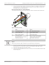
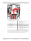
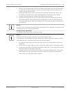
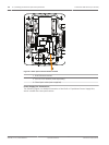
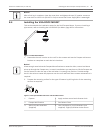
Figure 8.2: VG4-A-PSU1 or VG4-A-PSU2 Power Supply Box Connected to Pipe Interface Board
VG4-A-PSU1/VG4-A-PSU2 Pipe Interface Board
1 120 VAC/230 VAC Power In 7 P101 Connector
2 P101 Connector 8 P107 Connector
3 Ground Connection 9 24 VAC Power In (to camera)
4 Transformer 10 Earth Ground
5 24 VAC Power Out 11 24 VAC Power In (to camera)
6 P107 Connector 12 24 VAC Power In (to Heater)
13 24 VAC Power In (to Heater)
14 Camera Power
15 Heater Power
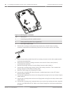
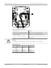
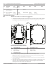
Wiring the Power Supply Box
Notice!
Refer to the Connection, page 70 chapter for wire specifications and distances.
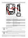
4 Route the high voltage 115/230 VAC lines through the earth-grounded conduit fitting on
the left side of the box.
Notice!
The Power Supply Box with transformer comes with a barrier that separates the high voltage
side on the left from the low voltage 24 VAC side on the right.
42 en | Installing the Roof Parapet and Pipe Mounts AutoDome 7000 Series (IP and HD)
2013.07 | 1.2.2 | F.01U.283.679 Operation Manual Bosch Security Systems