


119
Using the GPI I/O Connector
Chapter
Chapter 6 Control Using External Devices
6
Control Using External
Devices
Using the GPI I/O Connector
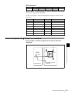
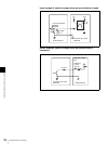
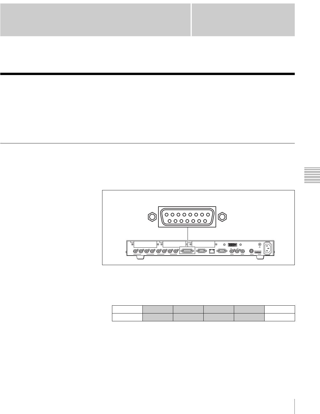
When the GPI I/O connector on the switcher is connected to the tally connector
on the camera control unit (CCU), etc., the tally lamp illumination on a camera
can be controlled by the switcher, or switching of the PGM and NEXT select
buttons on the switcher can be controlled by an external device.
Assigning Various Functions to the Pins on the GPI I/O Connector
All the pins are set to NOP (not used) at the factory. Use the menu to assign
various functions to pins 1 to 12 on the GPI I/O connector.
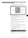
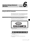
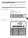
Pin assignments on the GPI I/O connector (D-sub 15-pin, female)
1
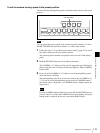
Display menu page 961.
For the procedure for displaying the menu, see “Menu Operation” on page
46.
2
Turn the F1 control to select pin number whose function you wish to change
under “PIN NO.”
You can select pin number 1 to 12.
3
Turn the F2 control to set the function of the selected pin under
“FUNCTION.”
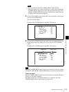
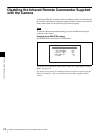
UTILITY PIN NO FUNCTION COLOR I/O DIR 1/3
GPI
1 NOP ----- Input 961
GPI I/O
5678
121314
1234
10 91115
1234PGM1 PGM2 AUX1
SDI OUTSDI IN
AUX2 REF IN REF OUT
RS-232C
~
AC IN
RS-422
DVI-I OUT
GENLOCK VISCA
GPI I/O PANEL LAN(10/100) REMOTE
IN1 IN2 OUT