


140
Menu List
Appendix
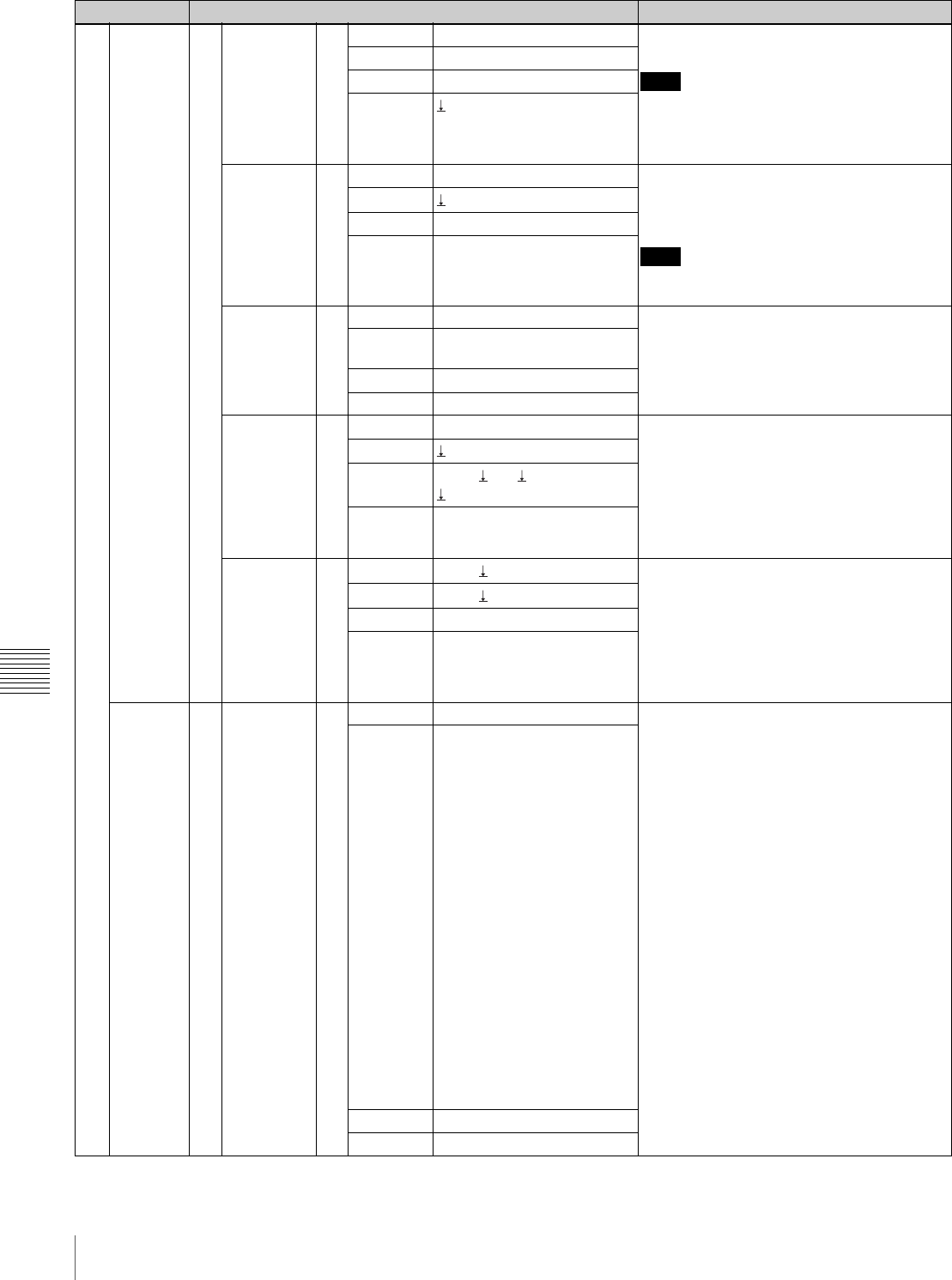
Setting menu Setting item Description
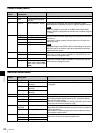
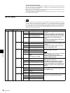
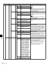
900 SYSTEM.. 950 SYSMODE.. 951 FORMAT SD, HD Selects the system that the switcher
supports.
Note
When FORMAT is set to HD and ASPECT is
set to 4:3 on menu page 951, a PGM or PVM
output image will remain in the portions
outside the 4:3 display.
FRAME 59.94, 50
ASPECT 4:3, 16:9
APPLY
Exec
REFIN.. 952 TYPE Tri Sync, BB Sets input sync signal.
When the F2 control (APPLY) is pressed after
setting TYPE, rebooting is required to enable
the setting.
Note
If FORMAT is set to SD on menu page 951,
TYPE is fixed to BB.
APPLY
Exec
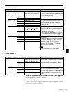
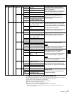
REFOUT.. 953 TYPE Tri Sync, BB Sets output sync signal.
When V PHASE is set to + 1H, 1H delay
occurs.
H PHASE –0.500 to 0.500 (0.000) (in
0.001, unit: H Line)
V PHASE –1H, 0H, +1H (unit: Line)
SNAP.. 954 MEM NO. 0 to 99 Resets the data stored in snapshot to the
factory preset value.
• To reset an individual snapshot number,
select the snapshot number under MEM
NO. then press the F2 control (MEM CLR).
• To reset data in units of Bank, select the
Bank number under CLR BANK then press
the F3 control (CLR BANK).
MEM CLR
Exec
CLR BANK
NOP, All, Bank 0 to
Bank 9
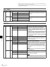
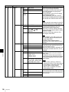
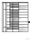
INIT.. 955 SETUP
NOP, Reboot
Resets the data stored in the switcher to the
factory preset value.
• To reset the SETUP data (menu pages
900s), turn the F1 control to display Reboot
then press the F1 control.
• To reset all the data including snapshot
data, turn the F2 control to display Reboot
under FACT SET then press the F2 control.
FACT SET
NOP, Reboot
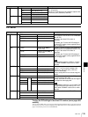
UTILITY.. 960 GPI.. 961 PIN NO 1 to 12 Sets input/output of the GPI I/O connector.
Turn the F1 control to specify the pin number
of the GPI I/O connector then turn the F2
control to select the function.
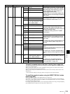
When any of Button1 to 12 is selected, turn
the F3 control to specify the illumination
color.
I/O DIR indicates whether the selected
function is for input or output.
FUNCTION NOP,
PGMBTN1 to PGMBTN12,
NEXTBTN1 to NEXTBT12,
AUX1BTN1 to AUX1BT12,
AUX1BTPG, AUX1BTPV,
AUX1BTMV, AUX2BTN1 to
AUX2BT12, AUX2BTPG,
AUX2BTPV, AUX2BTMV,
CUT, ME AUTO, PIP AUTO,
DSK AUTO, TRANSMIX,
TRANS WP, FRZ MEM1,
FRZ MEM2, CAM MODE,
SW MODE, DRCT-SS,
DRCT-WP, DRCT-PIP,
DRCTRCL0 to DRCTRCL9,
Button1 to Button12, DSK
On, PIP On, CAM1 to CAM7,
AUX1BTN1 to AUX1BT12,
AUX1BTPG, AUX1BTPV,
AUX1BTMV, AUX2BTN1 to
AUX2BT12, AUX2BTPG,
AUX2BTPV, AUX2BTMV
COLOR -----, Red, Amber
I/O DIR Input, Output (indication)