


30
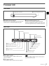
Processor Unit
Chapter 2 Locations and Functions of Parts
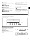
c OUT (output) card slot
Insert the BRSA-20DD2 interface board (not supplied).
d DVI-I OUT (DVI-I output) connector
Connect to the DVI input connector on a monitor.
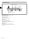
e U (ground) terminal
Used to connect to a ground lead.
Connect a ground lead when you use this switcher.
f ~ AC IN connector
Connect to an AC outlet with the supplied power cord.
g SDI IN (SDI input) 1 to 4 connectors (BNC type)
Input an SDI signal from a video camera or VCR (player).
You can input the SDI signal from 1 to 4 connectors. The
built-in frame synchronizer enables input of asynchronous
signals.
The switcher cannot accept SD-SDI and HD-SDI signals
simultaneously. Select SD-SDI or HD-SDI signal using
the menu.
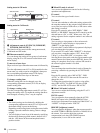
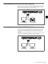
h PGM1 (program 1)/PGM2 (program 2) output
connectors (BNC type)
Connect to the SDI input connector on a monitor. The
program video with an effect applied is output via these
connectors. The same signal is output through the PGM1
and PGM2 connectors.
i AUX1 (auxiliary 1)/AUX2 (auxiliary 2) output
connectors (BNC type)
Connect to the SDI input connector on a monitor. The
PGM (program), PVW (preview) or MV (multi-viewer)
video signal, or any of the input signals selected with 1 to
12 buttons in the cross-point bus section can be output via
these connectors. The AUX1 and AUX2 output connectors
are able to output different signals.
j GPI I/O (GPI
*
input/output) connector (D-sub 15-
pin)
Connect to the tally connector on the video camera to
enable the tally lamp on the camera to light up. With the
switcher connected via this connector to an external
device, you can control the PGM or NEXT select buttons
on the switcher from the connected device.
* General-Purpose Interface
k PANEL (control panel) connector (D-sub 9-pin)
Connect to the PROCESSOR connector on the Control
Panel with the supplied control cable.
Be careful not to use the wrong connector as the
qa PANEL connector and qd REMOTE connector are the
same connector type.
l LAN (10/100) connector
Connect to a computer with a cross-type LAN cable (not
supplied). You can store the setting data for the switcher in
the connected computer and import the data from the
computer.
For safety, do not connect the connector for peripheral
device wiring that might have excessive voltage to this
port. Follow the instructions for this port.
When you connect the LAN cable of the unit to peripheral
device, use a shielded-type cable to prevent malfunction
due to radiation noise.
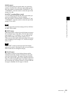
m REMOTE connector (D-sub 9-pin)
This connector is used for system expansion.
n REF IN (reference sync input) connectors (BNC
type)
A reference synchronization signal is input via this
connector from an external device. The other REF IN
connector is used as a loop-through output connector. If it
is not to be used as a loop-through output, attach a 75-ohm
terminator to this connector.
o REF OUT (reference sync output) connector (BNC
type)
If a reference synchronization signal is not input via the
REF IN connector, the built-in reference synchronization
signal is output through this connector.
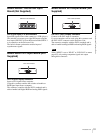
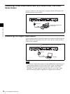
p RS-232C connector (mini-DIN 8-pin)
Connect to the VISCA RS-232C connector on a camera.
q RS-422 connector (Connector plug)
Connect to the VISCA RS-422 connector on a camera
using the supplied RS-422 connector plug (5-pin).
For connection using the RS-422 connector plug, see “To
Use the VISCA RS-422 Connector Plug” on page 151.
For VISCA connection, be sure to use either connection
using the RS-422 or the RS-232C connector.
Note
Note
CAUTION
CAUTION
Note