


54
Basic Setups for the Switcher
Chapter 3 Preparations
Setting Up the Video Output Signals
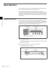
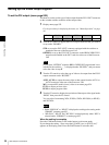
To set the DVI output (menu page 932)
The menu is used to set the type of video output from the DVI-I OUT connector
on the switcher and the resolution of that output video.
1
Display menu page 932.
For the procedure for displaying the menu, see “Menu Operation” on page
46.
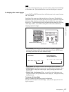
2
Turn the F1 control to display the DVI-I output connector that you wish to
set up under “BOARD.”
STD: to set up the DVI-I OUT connector equipped with the switcher as
standard at the rear of the Processor Unit
OPTION: to set up the DVI-I OUT connector on the BRSA-20DD2 DVI
output board installed in the OUT card slot at the rear of the Processor
Unit
If you select “OPTION” when the BRSA-20DD2 DVI output board is not
installed in the switcher, “_” is displayed under “BUSSEL,” and you cannot
select the video in step 3.
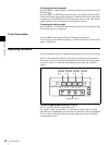
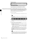
3
Turn the F2 control to select the type of video to be output from the DVI-I
output connector under “BUSSEL.”
AUX1, AUX2: to output the same video as that output from the AUX1 or
AUX2 connector at the rear of the Processor Unit
MV: to output MV (multi-viewer) video set on menu page 934
PVW: to output preview video
PGM: to output program video
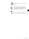
4
Turn the F3 control to display the resolution of the output video signal under
“RESO” then press the F3 control.
You can select from among XGA, WXGA, SXGA, HD 59.94 (or HD 50)
and WUXGA.
• Either “HD 59.94” or “HD 50” is displayed according to the setting under
“FRAME” on menu page 951.
• “HD 59.94,” “HD 50” and “WUXGA” are displayed only when “HD” is
selected under “FORMAT” on menu page 951.
When the setting is complete
Press the CAM mode button or SW mode button to exit menu mode.
If you change the setting, “Save setup data? [PAGE] (yes) or [EXIT] (no)”
appears on the display panel. Press the PAGE button to store the data.
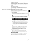
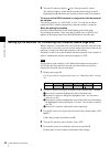
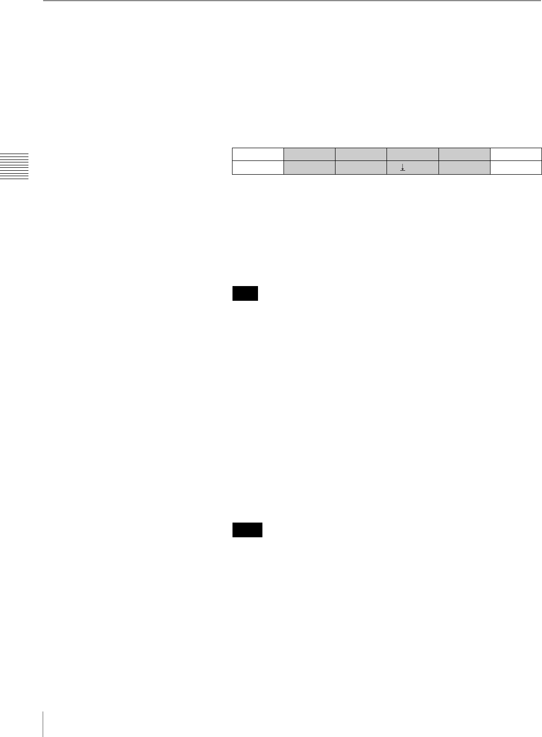
OUTPUT BOARD BUSSEL RESO 2/6
DVI
STD PGM
XGA
932
Note
Notes