


29
Processor Unit
Chapter 2 Locations and Functions of Parts
Processor Unit
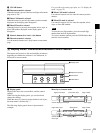
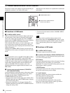
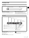
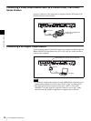
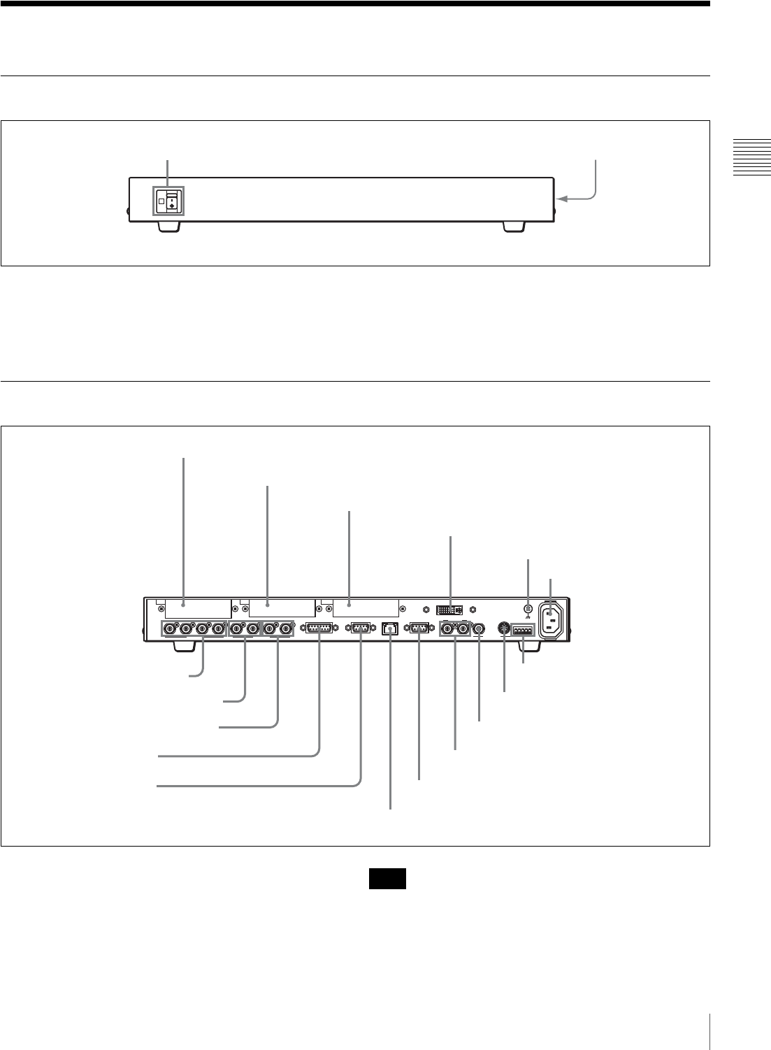
Front Panel
a POWER switch and indicator
Turns the Processor Unit ON/OFF. Press the ? side of the
switch to turn it on. The indicator lights up in green.
b Rack mounting attachment screws
Use these screws to attach the supplied rack mount
brackets for installing the switcher in a rack. Four screws
each on the right and left sides are attached at the factory.
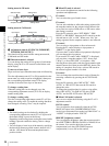
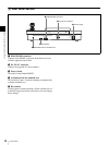
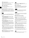
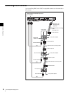
Rear Panel
a IN1 (input 1) card slot
Insert the BRSA-20HSD1 or BRSA-20DD1 interface
board (not supplied).
b IN2 (input 2) card slot
Insert the BRSA-20DD1 interface board (not supplied).
The optional BRSA-20HSD1 interface board cannot be
installed in the IN2 card slot.
POWER
OFF
ON
1 POWER switch and indicator
2 Rack mounting attachment screws
1
IN1
234PGM1 PGM2 AUX1
SDI OUTSDI IN
AUX2 REF IN REF OUT
RS-232C
~AC IN
RS-422
DVI-I OUT
GENLOCK VISCA
GPI I/O PANEL LAN(10/100) REMOTE
IN2 OUT
7 SDI IN 1 to 4 connectors
1 IN1 card slot
2 IN2 card slot
3 OUT card slot
8 PGM1/PGM2 output connectors
4 DVI-I OUT connector
5 U (ground) terminal
6 ~ AC IN connector
qs LAN (10/100) connector
qd REMOTE connector
qf REF IN connector
qg REF OUT connector
qh RS-232C connector
qj RS-422 connector
9 AUX1/AUX2 output connectors
q; GPI I/O connector
qa PANEL connector
Note