


37
Connecting External Equipment
Chapter 3 Preparations
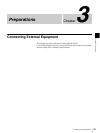
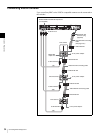
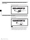
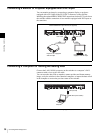
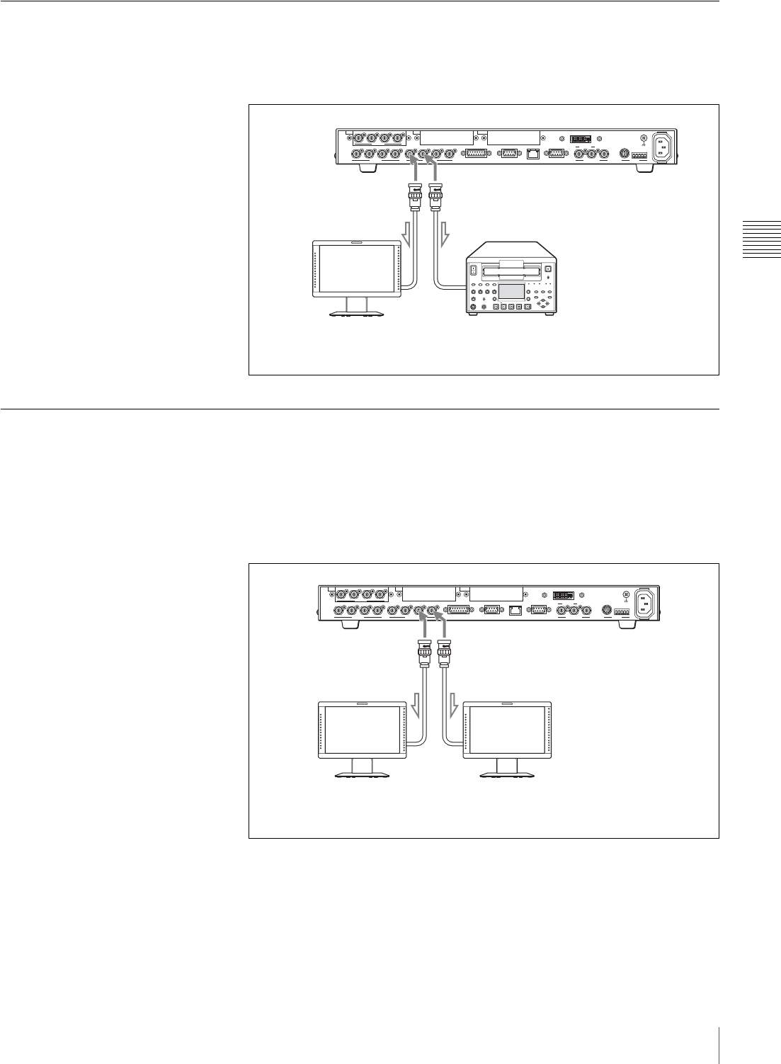
Connecting Monitors to the PGM1 And PGM2 Connectors
Program videos are output from the PGM1 and PGM2 connectors. These two
connectors output the same signal. Connect the PGM1 and PGM2 connectors
on the switcher to the SDI inputs on a monitor or VCR.
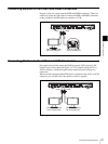
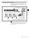
Connecting Monitors to the AUX1 And AUX2 Connectors
One signal selected from among the PGM (program), PVW (preview), MV
(multi-viewer) videos and input signals 1 to 12 is output from the AUX1 or
AUX2 connector. A different signal can be output from each of these two
connectors.
When a monitor equipped with an SDI input is connected to the AUX1 or AUX2
connector, you can check the video before an effect is applied.
1234PGM1 PGM2 AUX1
SDI OUTSDI IN
5678
SDI IN
AUX2 REF IN REF OUT
RS-232C
~
AC IN
RS-422
DVI-I OUT
GENLOCK VISCA
GPI I/O PANEL LAN(10/100) REMOTE
IN1 IN2 OUT
–
+
–
+
–
+
–
+
–
+
–
+
VCR, etc. equipped
with an HD-SDI input
PGM2
PGM1
Monitor, etc. equipped
with an HD-SDI input
1234PGM1 PGM2 AUX1
SDI OUTSDI IN
5678
SDI IN
AUX2 REF IN REF OUT
RS-232C
~
AC IN
RS-422
DVI-I OUT
GENLOCK VISCA
GPI I/O PANEL LAN(10/100) REMOTE
IN1 IN2 OUT
–
+
–
+
–
+
–
+
–
+
–
+
–
+
–
+
–
+
–
+
–
+
–
+
Monitor, etc. equipped
with an HD-SDI input
AUX2
AUX1
Monitor, etc. equipped
with an HD-SDI input