


40
Installation and Connection of the Switcher
Chapter 3 Preparations
Installation and Connection of the Switcher
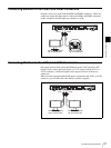
This section describes installation and connection of the switcher.
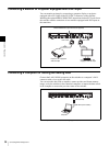
Installing an Interface Board
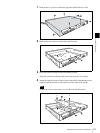
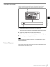
Install an optional interface board in the card slot at the rear of the Processor
Unit. The Processor Unit has three card slots at the rear. Some of the interface
boards are restricted with regard to installation in some of these three card slots.
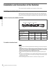
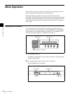
Interface boards and available card slots
Yes: can be installed, No: cannot be installed
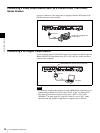
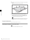
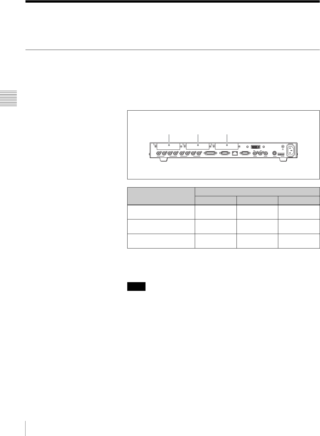
To install an interface board
• Be sure to turn off all the equipment before attaching or removing an interface
board.
• Immediately after the switcher has been turned off, the Processor Unit is
hot. Be sure to wait more than 30 minutes after the switcher is turned off
before you open the top cover of the Processor Unit.
• Do not remove any panels inside other than the top panel of the Processor
Unit.
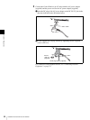
• Be sure to use the attachment screws supplied with an interface board to install
it in the card slot. Using other screws may cause damage to the interface board
and the Processor Unit.
• When installing the interface board, be careful not to injure yourself.
Interface board
Card slot
IN1 IN2 OUT
BRSA-20HSD1 HD/SD-SDI
input board
Ye s N o N o
BRSA-20DD1 DVI input
board
Ye s Ye s N o
BRSA-20DD2 DVI output
board
No No Yes
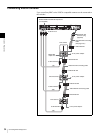
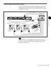
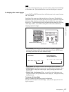
1234PGM1 PGM2 AUX1
SDI OUTSDI IN
AUX2 REF IN REF OUT
RS-232C
~
AC IN
RS-422
DVI-I OUT
GENLOCK VISCA
GPI I/O PANEL LAN(10/100) REMOTE
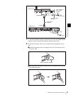
IN1 IN2 OUT
IN1 card slot IN2 card slot OUT card slot
Notes