


31
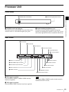
Processor Unit
Chapter 2 Locations and Functions of Parts
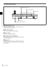
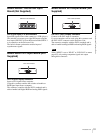
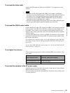
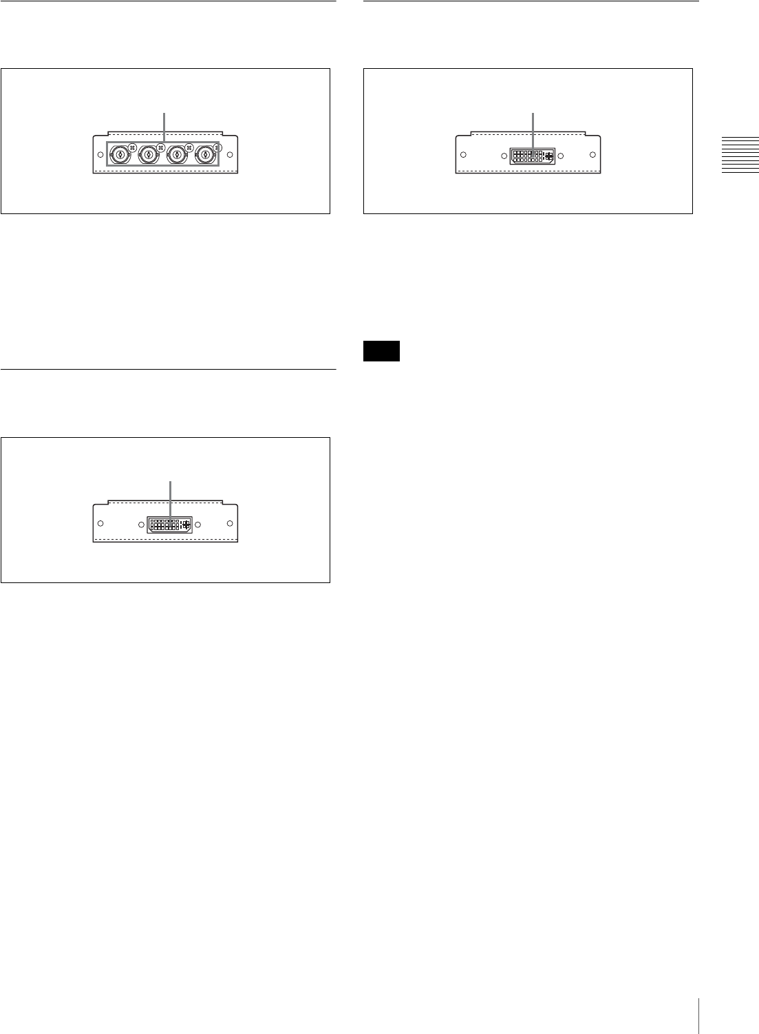
BRSA-20HSD1 HD/SD-SDI Input
Board (Not Supplied)
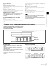
SDI IN (SDI input) 5 to 8 connectors
Input SDI signals from a video camera or a VCR (player).
The switcher can accept up to eight SDI inputs using the
four inputs (SDI IN 5 to 8) on this board and the SDI IN 1
to 4 connectors on the Processor Unit.
The built-in frame synchronizer enables input of
asynchronous signals.
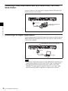
BRSA-20DD1 DVI Input Board (Not
Supplied)
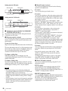
DVI-I IN (DVI-I input) connector
Inputs a DVI signal from a computer.
Using this connector enables the switcher to handle an
RGB signal input from a computer.
The connector complies with the DVI-I standards and is
able to handle both digital RGB and analog RGB signals.
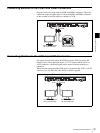
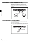
BRSA-20DD2 DVI Output Board (Not
Supplied)
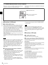
DVI-I OUT (DVI-I output) connector
Connect to the DVI input on a monitor.
Up to two monitors can be used, using this connector and
the DVI-I OUT connector on the Processor Unit.
The connector complies with the DVI-I standards and is
able to handle both digital RGB and analog RGB signals.
When “RESO” is set to “HD 50” or “HD 59.94” on menu
page 932, only analog component signals are output
through this connector.
5678
SDI IN
SDI IN 5 to 8 connectors
DVI-I IN
DVI-I IN connector
Note
DVI-I OUT
DVI-I OUT connector