


7-13
Cisco ONS 15600 Reference Manual, R7.2
Chapter 7 Circuits and Tunnels
7.4.2 IP-Encapsulated Tunnels
7.4.2 IP-Encapsulated Tunnels
An IP-encapsulated tunnel puts an SDCC in an IP packet at a source node and dynamically routes the
packet to a destination node. To compare traditional DCC tunnels with IP-encapsulated tunnels, a
traditional DCC tunnel is configured as one dedicated path across a network and does not provide a
failure recovery mechanism if the path is down. An IP-encapsulated tunnel is a virtual path, which adds
protection when traffic travels between different networks.
IP-encapsulated tunneling has the potential of flooding the DCC network with traffic resulting in a
degradation of performance for CTC. The data originating from an IP tunnel can be throttled to a
user-specified rate, which is a percentage of the total SDCC bandwidth.
Each ONS 15600 supports up to 128 IP-encapsulated tunnels. You can convert a traditional DCC tunnel
to an IP-encapsulated tunnel or an IP-encapsulated tunnel to a traditional DCC tunnel. Only tunnels in
the DISCOVERED status can be converted.
Caution
Converting from one tunnel type to the other is service-affecting.
7.5 Multiple Destinations for Unidirectional Circuits
Unidirectional circuits can have multiple destinations (drops) for use in broadcast circuit schemes. In
broadcast scenarios, one source transmits traffic to multiple destinations, but traffic is not returned to
the source. The ONS 15600 supports one of the following:
•
Up to 2048 1:2 nonblocking broadcast connections
•
Up to 682 1:n nonblocking broadcast connections (where n is less than or equal to 8)
When you create a unidirectional circuit, the card that does not have its backplane receive (Rx) input
terminated with a valid input signal generates a Loss of Signal (LOS) alarm. To mask the alarm, create
an alarm profile suppressing the LOS alarm and apply the profile to the port that does not have its Rx
input terminated. To create an alarm profile, refer to the “Manage Alarms” chapter in the
Cisco ONS 15600 Procedure Guide.
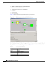
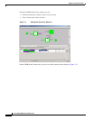
7.6 Path Protection Circuits
Use the Edit Circuit window to change path protection selectors and switch protection paths
(Figure 7-4). In the path protection Selectors subtab in the Edit Circuits window, you can:
•
View the path protection circuit’s working and protection paths.
•
Edit the reversion time.
•
Set the hold-off timer.
•
Edit the Signal Fail (SF) and Signal Degrade (SD) thresholds.
•
Change Path Payload Defect Indication (PDI-P) settings.
Note
In the UPSR Selectors tab, the SF Ber Level and SD Ber Level columns display “N/A” for those nodes
that do not support VT signal bit error rate (BER) monitoring.