


2-19
Cisco ONS 15600 Reference Manual, R7.2
Chapter 2 Card Reference
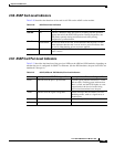
2.7.4 OC192/STM64 SR/SH 4 Port 1310 Network-Level Indicators
2.7.4 OC192/STM64 SR/SH 4 Port 1310 Network-Level Indicators
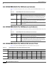
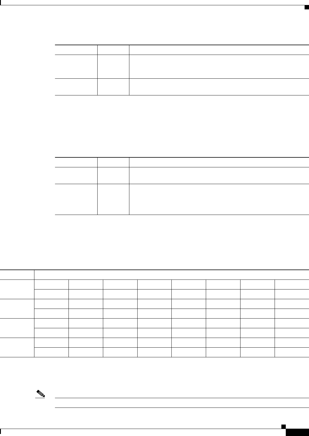
Table 2-17 describes the functions of the network-level LEDs on the OC192/STM64 SR/SH 4 Port 1310
card.
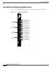
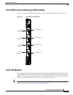
2.7.5 OC192/STM64 SR/SH 4 Port 1310 Card OGI Connector Pinout
Table 2-18 lists the OC192/STM64 SR/SH 4 Port 1310 card OGI connector pinouts.
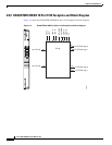
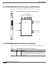
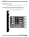
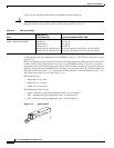
2.8 ASAP Card
Note
For card specifications, see the “A.2.7 ASAP Specifications” section on page A-11.
SRV LED
Green The service mode of the card. Green indicates that the card is in use,
amber indicates that the card is out of service, and off indicates that the
card is either booting or has no power applied.
LASER ON
Green The green LASER ON LED indicates that at least one of the card’s
lasers is active.
Table 2-16 OC192/STM64 SR/SH 4 Port 1310 Card-Level Indicators (continued)
Indicator Color Description
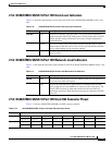
Table 2-17 OC192/STM64 SR/SH 4 port 1310 Network-Level Indicators
Indicator Color Description
SD LED
Blue The blue SD LED indicates a signal degrade or condition such as a low
signal level on at least one of the card’s ports.
SF LED
Red The red SF LED indicates a signal failure or condition such as LOS,
LOF, or high BER on at least one of the card’s ports. The red SF LED
also turns on when the transmit and receive fibers are incorrectly
connected. When the fibers are properly connected, the LED turns off.
Table 2-18 OC192/STM64 SR/SH 4 Port 1310 Card OGI Connector Pinout
Connector OGI Pin and Card Port
112345678
— — Transmit 1 Receive 1 — — — —
212345678
— — Transmit 2 Receive 2 — — — —
312345678
— — Transmit 3 Receive 3 — — — —
412345678
— — Transmit 4 Receive 4 — — — —