


1-2
Cisco ONS 15600 Reference Manual, R7.2
Chapter 1 Shelf and Backplane Hardware
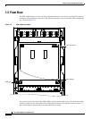
1.2 Bay Installation
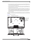
door of the ONS 15600 allows access to the shelf assembly, fan-tray assembly, and cable-management
area. The customer access panel (CAP) on the back of the shelf provides access to alarm contacts,
external interface contacts, and timing contacts. Power and ground terminals are located on the top left
and right sides of the bay.
Caution
Voltage to the alarm circuits should not exceed –48 VDC.
The ONS 15600 comes mounted in a custom, certified NEBS-2000 rack. The bay assembly, including
the rack, fan trays, and PDU weighs approximately 500 pounds (226.8 kg) with no cards installed.
ONS 15600 OC-N cards have OGI connectors on the card faceplate; available connector termination
types are SC, ST, and FC. Fiber optic cables are routed to the front of the OC-N cards.
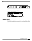
The ONS 15600 is powered using –48 VDC power but may range from –40.5 to –72 VDC. Input power
is accessible from the sides of the bay, and output power is accessible at the rear of the bay. Cisco
supports dual office-power feeds only.
Install the ONS 15600 in compliance with your local and national electrical codes:
•
United States: National Fire Protection Association (NFPA) 70; United States National Electrical
Code
•
Canada: Canadian Electrical Code, Part I, CSA C22.1
•
Other countries: If local and national electrical codes are not available, refer to IEC 364, Part 1
through Part 7.
1.2 Bay Installation
In this chapter, the terms “ONS 15600” and “bay assembly” are used interchangeably. In the installation
context, these terms have the same meaning. Otherwise, bay assembly refers to the physical steel
enclosure that holds the shelves and power distribution unit (PDU), and ONS 15600 refers to the entire
system, both hardware and software.
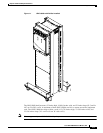
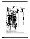
To install the ONS 15600, you must first unpack the bay assembly. Two custom ramps and two dollies
are available to assist you with the removal of the bay from the shipping pallet and transportation to the
installation location. Figure 1-1 shows the bay assembly with the dollies installed.