


2-5
Cisco ONS 15600 Reference Manual, R7.2
Chapter 2 Card Reference
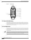
2.2.3 TSC Card-Level Indicators
2.2.3 TSC Card-Level Indicators
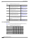
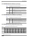
Table 2-3 describes the functions of the card-level LEDs on the TSC card faceplate.
2.2.4 TSC Network-Level Indicators
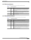
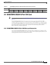
Table 2-4 describes the functions of the network-level LEDs on the TSC card faceplate.
Table 2-3 TSC Card-Level Indicators
Indicator Color Definition
STAT
Red Indicates a hardware fault; this LED is off during normal operation.
Replace the card if the STAT LED persists. During diagnostics, the LED
flashes quickly during initialization and slowly during configuration
synchronization.
SRV
Green The service mode of the card. Green indicates that the card is in use,
amber indicates that the card is out of service, and off indicates that the
card is either booting or has no power applied.
ACT/STBY
Green The ACT/STBY (Active/Standby) LED indicates that the TSC is active
(green) or standby (off).
Table 2-4 TSC Network-Level Indicators
Indicator Color Definition
LINE
Green Node timing is synchronized to a line timing reference.
EXTERNAL
Green Node timing is synchronized to an external timing reference.
FREE RUN
Green Node is not using an external timing reference. Indicated when the
timing mode is set to an internal reference or after all external references
are lost.
HOLDOVER
Amber External/line timing references have failed. The TSC has switched to
internal timing and the 24-hour holdover period has not elapsed.
ACO
Amber The alarm cutoff (ACO) push button has been activated. After pressing
the ACO button, the amber ACO LED turns on. The ACO button opens
the audible closure on the backplane. The ACO state is stopped if a new
alarm occurs. After the originating alarm is cleared, the ACO LED and
audible alarm control are reset.