


1-14
Cisco ONS 15600 Reference Manual, R7.2
Chapter 1 Shelf and Backplane Hardware
1.9 Power and Ground Description
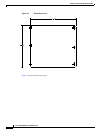
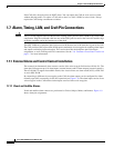
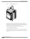
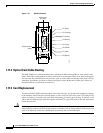
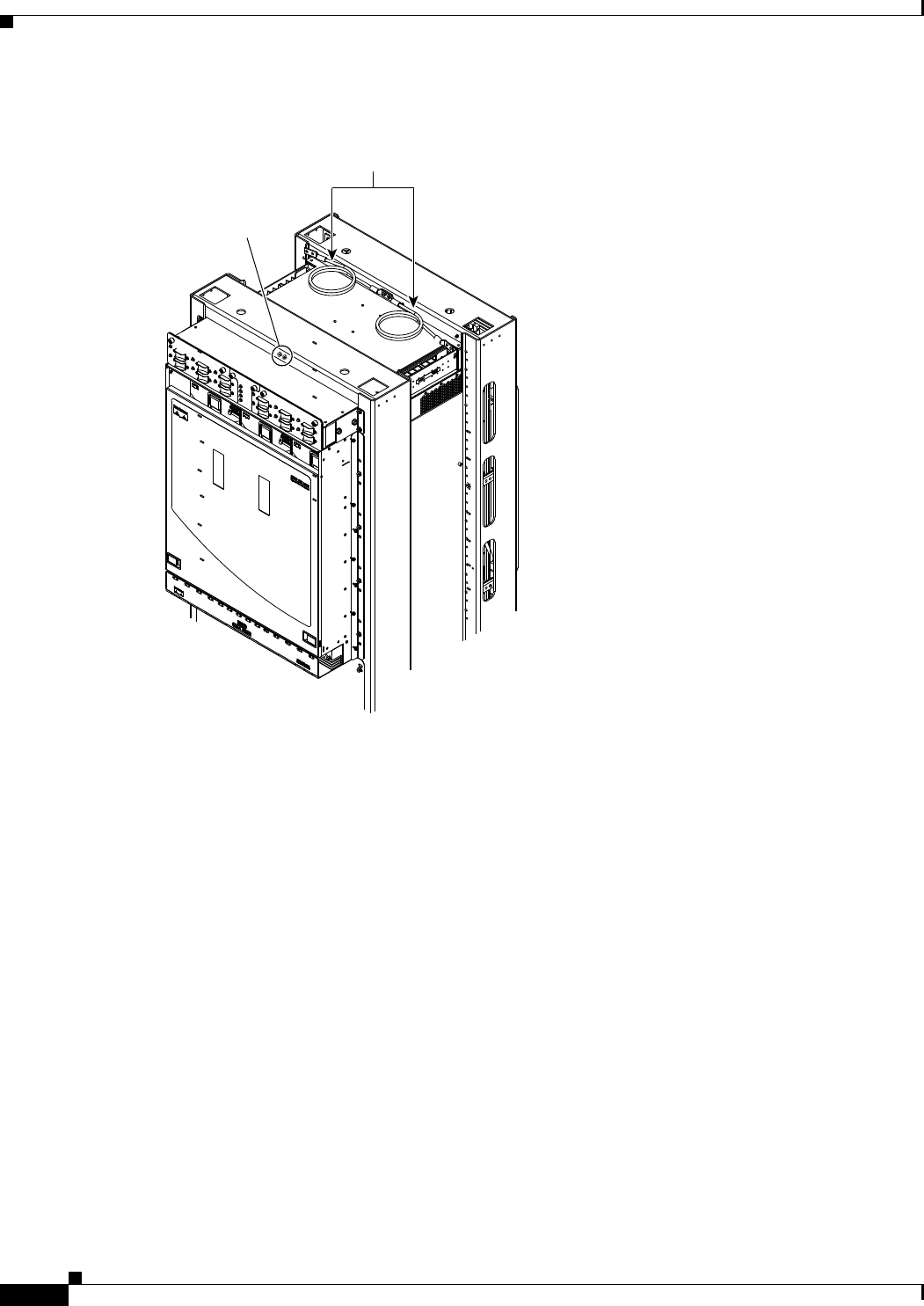
Figure 1-11 Front and Rear Bay Ground Holes
The main power connections are made at the PDU side terminals at the top of the bay. To install
redundant power feeds, use four power cables and ground cables. For a single power feed, only two
power cables and one ground cable (all rated for at least 125-A capacity) are required. Use a conductor
with low impedance to ensure circuit overcurrent protection. The ground conductor must have the
capability to safely conduct any faulty current that might be imposed.
Cisco recommends the following wiring conventions, but customer conventions prevail:
•
Red wire for battery connections (–48 VDC)
•
Black wire for battery return connections (0 VDC)
•
The battery return connection is treated as DC-I, as defined in Telcordia GR-1089-CORE, issue 3
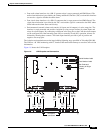
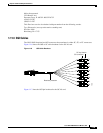
The ONS 15600 shelf has redundant –48 VDC power terminals on its backplane. The terminals are
labeled A FEEDS and B FEEDS and are located at the top left and right sides of the shelf behind clear
plastic covers.
96611
PDU frame
ground cable
Bay grounding
holes